Steve’s been in touch – have a look at his way for detecting trains:
“Hi Al,
Detecting trains on the layout can be very useful.
I Just thought I might share this little trick that I have developed. It is a simple, cheap, and very reliable method using just 3 resistors.
I use this method to:
-
To operate a crossing
A train position indicator
Signalling
To activate an announcement or sound
The advantages of this circuit are:
- Cheap and easy to build
Works with any power mode, DC, DCC, battery etc
Can work with any power supply
Output can be adjusted to interwork with any other device
Small current drain
Take two ‘light dependent resistors’.
One is placed under the track (r2), and the other (r1) is placed anywhere alongside the track. Connect the resistors together.
Connect voltage to the other side of r1. Connect the centre contact of a 50k variable resistor (trimpot, r3) the other side of r2.
Connect 0v to one side of r3. Adjust r3 to achieve the required output voltage from the centre connector.
All of these devices are simple, cheap, and can be obtained from any electronics retailer, or ebay.
The circuit is:
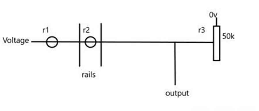
At normal, the three resistors make up a voltage divider, so that the output from r3 can be adjusted as required.
When a train passes over r1, its resistance goes much higher, reducing the output.
This output can then be used for almost any other circuit via transistor, microprocessor, LED etc.
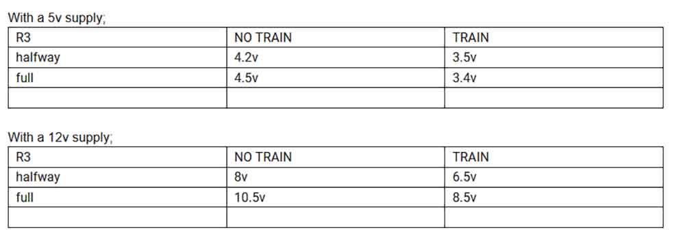
The values of r1 and r2 were 2k at normal (4.5k when dark), but nearly any approximate value will work because r3 is used to obtain whatever value you require.
R2 is essential as it acts as a compensator for varying light conditions around the layout, or for night time running. If the light level alters, both r1 and r2 will change at a similar rate. This keeps the voltage divider ratios about equal.
For DC users, the voltage onto R1 could be taken from the NORTH rail (positive), and ov from SOUTH rail. But output will always depend on the input voltage. So a train moving slowly will not provide 12v (more like 6v). Also, a train moving in reverse will provide a different output.
Regards
Steve (Sydney)”
Clever stuff from Steve when it comes to detecting trains.
And now on to a subject I’m very keen on: making a start!
“Hello Al,
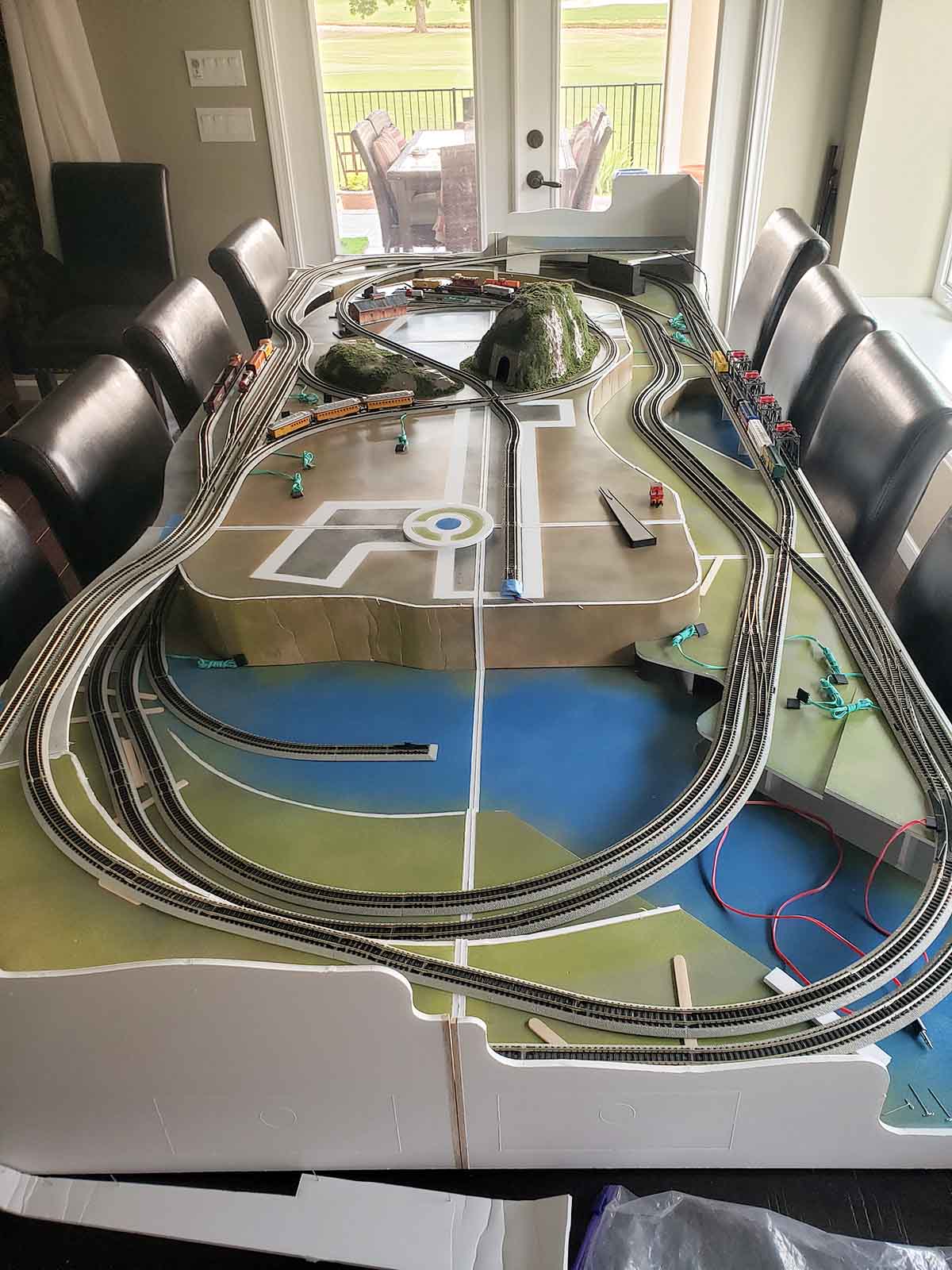
We finally made a start on the layout.
I love reading your post and your latest hall of fame inductees are well deserving, so congrats to the dynamic duo.
We decided to use RRinabox for the modules and then we have kit bashed it to redesign the extra track…our oldest son has gotten involved and he is way smarter than us. So it may get to suffisticated for Vicki and I to run.
There are 3 continuous loops that we can switch and run a train from outside upper loop all the way to inside lower loop and back out.
Its kind of cool and takes about 18 minutes with some operations of manually switching turnouts and crossovers.
The layout is currently 42″ x 96″ and we do have a plan to later add another module for the saw mill.
That’s all for now and we will send more pictures as we progress.
Your Texas fans,
Sid and Vicki”
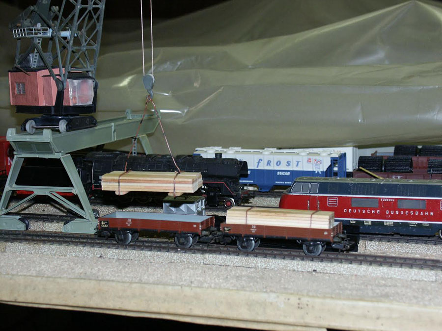
“Hello Alastair,
The pictures show a load of lumber (HO) that I made from ice cream sticks. They are glued together and thin brown wires were used for tie-downs.
Guenter”
I kiked Guenter’s lumber trucks – simple but effective, like most of your wonderful tips and pics.
Lastly, a question from John which I thought worth posting, as I’m sure it would help others in the interest of making a start:
“Alastair, I have been a member so to speak for several years and I have finally acquired a room for a layout.
For me when I say “just starting out” I mean it.
Haven’t built a layout for several years due to lack of space. DCC, which is what I want, is new to me and my question to you is: what do I start with?
I am working on a 8X10 HO layout to begin with. Engines, cars, track, switches etc.
Any help would be greatly appreciated. I have really appreciated your work on the blog and all of the additional comments made by so many people.
Sincerely,
John “Red Label” Walker”
Please do leave a comment below if you can help.
A big thanks to Steve, Sid and Vicki.
All these years in and it’s still wonderful to see your solutions to specific problems.
And of course, it’s great to see those ‘starts’ because that’s where the magic is.
That’s all for the this time.
Please do keep ’em coming.
And if today is the day you get started on your layout, the Beginner’s Guide is here.
Best
Al
PS Latest ebay cheat sheet is here.

Steve,
I am not sure I understand what your detectors “signals” or how? does it flip lights on a control panel, OR does it control an actual signal light for the trains? I’d LOVE to have you explain this for those of us DC “analog” control users! (I got a use for an easy detector for a small holiday display I made for Christmas! ANY help be greatly appreciated!
Al, can you please have Steve contact me on this? It be VERY helpful!
~Hemi
Hi John, You appear to have raised the track from Ground level to a level to cross the circle line, a little under 3″ in a very short space. On trying something similar, I found the Loco could not pull itself up such a steep gradient, let alone pull any wagons. I know once up there the high-level track is not yet finished, so it may be that you intend the train to only go down the single track and the assent will be less steep. All the best, and thanks for sharing your track plan and layout. Tom Lori, Reading, England
Hi Sid, A further comment. At the near end of the layout, the track crosses blue [water?] and drops down under the main layout. Does it re-appear at the far end of the layout, run under the rising track mentioned in comment 1, and complete the loop on the flat again, or am I seeing squiffy? In some ways it is rather like my layout, only it looks more interesting. Mine just goes up over 10′ to 3″ height, through a mountain tunnel to cross the gorge on a suspension bridge, and through the mountain on the other side of the gorge before descending back to ground level Thanks again for sharing. Tom Lori, Reading England
LMAO- Love idea of using dining room and table, who wants company. Layout is meticulous, hope to see sometime near finish.
John “Red Label”
I assume you are in the states so the big question is whether to buy NCE or Digitrax for your new system. I have and love the NCE basic for my HO with the understanding that 2 amps is the limit and can safely run 2 engines at one time. If there is any chance you may go above 2 amps and run more engines then you have to jump out of simple to a higher amp system and you have to also look at Digitrax as an option. I mention these two because they have great programming capabilities and more options than the simple Bachman system. I wish someone explained that to me when I started.
Steve, can you list the part numbers of the parts you used in your detector circuit.
Steve, in your explanation, don’t you mean the train moves over R2, since it’s under the track, and that R1 is the light level compensator?
Very useful circuit, though.
What a great track plan and a very neat and tidy layout. I really like this one. Great work. Rob McCrain – Farland Howe
Hi Al, & Rich B:
General observation, after reading the brief description of the Layout in the photos,,, the RRinabox is a Modular RR Layout you put together whenever
you want to run your layout… SO, the move logical place was the Dining
Room Table unless you find some other room, or basement or attic area
or the Garage to put the layout in permanently. Nice Clean Approach a
layout in the making… Will look more completed once buildings, trees,
vehicles and people are added.. Just my 2 cents from Mike in N.H. USA.
Looks pretty kool.!!!!!!!!!!! I hope mine turns out that good.
Jihn :”Red Label” Walker, before you any go further, stop for now and acquire
THE BEGINNER GUIDE, available right here on this site from Alastair, you wiil thamk yourself .later.
Léo from Québec, CA
When my children were much younger, I did, of course, try to encourage their interest in trains with a wooden toy train set at one Christmas. Of course, they loved it, as did I. This was also the day I “invented” a train detector, to wit, my bare foot.
Sid and Vicki
First, how did you get Vicki to give up her dining room table? You must be a a very persuasive guy.
Very interesting track plan. I assume it is HO. I like the interconnecting three ovals. You get a lot of operation in a very limited space. I’m copying you.
But what is your angle of elevation between levels? It looks a bit steep to me.
Incidentally. I’ve read of one modeler who mounted about six feet of track on a board that he incrementally raises at one end to test a locos “pulling power”
Sid and Vicki, I am also under constraints as the amount of space I have to build my layout. I love your layout and would like to build one just like it. If you would be so kind as to send me any pictures and other pertinent info regarding your layout I would greatly appreciate it. Thanking You in Advance, Steve.
From what John said and the picture, I believe his layout is N scale using Kato track. Since the track is sold as a kit, I’m sure the elevation slope is predetermined and workable. It’s an interesting plan for the size board, but I might not take up such a large area with the heliport, since it does use up so much scenic space and isn’t likely to be rail served. I would use it for an industrial or mixed local rail served businesses and/or residential area. Would allow for buildings and landscape that could cut the view into smaller scenes.But that’s just me.
As far as the train detector module, it’s a rather simple but dependable circuit but itlacks some explanation as to how it works. There are 2 photoresistors R1, R2, that change resistance with amount of light falling on them. R2 is installed pointed up where it can see the ambient light between the track rails where you want the detection, R1 is installed off the track nearby. R3 is an adjustable resistor that is used to “balance” R1 and R2. After balancing, both R1, and R2 “sees” an amount of ambient light. As long as the ratio of light hitting both remains the same, nothing happens. When the amount of light hitting R2 changes due to the shadow of a train passing over it, R1 and R2 become unbalance and the circuit “trips” supplying power to whatever is attached to the output. It remains tripped until the light ratio returns to it’s balanced state.
Scott J: yes, a typo and you are correct, Thank You.
Everyone: I will send more info thru to Al.
Thanks for the comments.
Steve (Sydney)
Dear Alaistair:
Please ask Steve, if he could give me his e-mail, in order to ask him some cuestions about his clever “detecting trains system”, my English is not as good as I desire, to understood the way he do it.
I live in Colombia South America, I am building my first layout (it’s medium size, 12′ x 16′, DC) and it will be very helpfull.
Thank you for all your wonderfull mails, I have your “Beguiners Guide” and some of your “paper buildings” they help me a lot with my budget, that is not quite big as I will desire.
Best regards
Juan C. Guerrero V.
good info. like the dinning room use. keep us informed with progress.
Great idea Steve using basic principles.
There are small relay modules that would be suitable for connection to this circuit. Jaycarr in Australia sells them but I am sure there are similar outlets in other countries.
nice love the table idea
Nice work Steve with the detector circuit ,
As I only have very basic skills with electronics and electrical I am generally a KISS modeller and as such love a cheap & simple idea.
As mentioned by others a materials list & typical example photo or two of what an installation would look like for a LED connected to the output and wiring, for say a simple track side signal / LED light as I am never going to connect it to a microprocessor, I am firmly stuck in the DC / analog age.
Picture is worth a thousand words and all that. Like some, I do love an ‘idiots guide’ approach to explain things.
I really appreciate all the efforts that people on this site
put in to sharing their experiences and knowledge, great stuff.