John’s been back in touch with an update on his Erie Lackawanna model railroad.
Here’s a pic from his last missive so you can see where he’s up to:
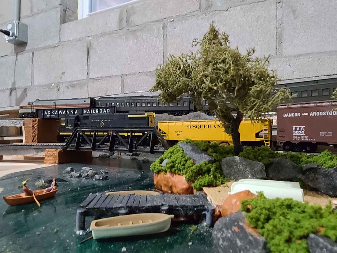
(John’s previous post is here: HO scale track layout.)
“Hi Al,
I thought I would give a rundown of where I am with the M&K Division of the Erie-Lackawanna in HO scale since I was last in contact with you several months ago.
It has been a busy spring and summer. I built a control panel and the desk on which it sits. The panel itself is a rectangular piece of 1/4″ plywood painted black on which I mounted a reverse loop selector (item #220) and several four-switch power selector units (item #215) from Atlas.
I mounted the control panel on the top of the desk using two door hinges, which allows me to pull the control panel back when I need to hook up new power blocks or make adjustments to what I have already installed.
Above the power controls are several remote control turnout switches for turnouts on the layout that are out of my reach to throw manually.
I have enough space to lay down a schematic of both the main and branch lines using white chart tape but I am waiting until I complete the trackwork on the unfinished portions of the layout to do so.
For now, I have crudely drawn the schematics on sheets of white paper that are mounted on the spot where the permanent ones will be located.
The construction of the desk itself is basically the same as the tables supporting the layout — 2x3s for the legs with adjustable feet, 1x3s for the desk frame and leg supports and a 1/2” thick piece of birch sanded plywood for the surface area.
The desk is wide enough to accommodate two Model Rectifier Corp. DC power packs flanking the control panel, which allow for simultaneous operation of two trains. I can fit two chairs underneath it.
The completion of what I will call the “central control center” allowed me to permanently wire all completed portions of the layout.
I added enough spare power selector units to accommodate the wiring for those yet-to-be finished layout sections. It took me three or four days to complete the wiring.
And, yes, as you can see from the photo, there are a LOT of wires.
But I guess that is the price to pay with a larger layout that ultimately will have upwards of 20 power blocks and several powered turnouts. But, it is manageable for me!
The most difficult part of it was the wiring of the reverse loop and selector, which allows me to connect the branch and main lines via the “Tyler Spur” between Marysville and Tyler Junction.
Tyler Spur is in essence a reverse loop because the electrical currents collide where the spur and main line meet (please excuse the lack of knowledge of the correct technical term for it).
I was at a loss at how to solve the issue until a vendor at a Greenberg Train Show here in New Jersey last winter suggested using the Atlas reverse loop selector.
Atlas provides pretty straightforward directions on the back of the reverse loop selector package but I still had some self-inflicted issues getting it to work.
I had to re-read the instructions several times before it all finally registered with me. The end result is that It works and that is all that matters, I guess.
I also took care of a few things that have bothered me about some completed sections of the layout. A couple involve train stalls.
Particularly troublesome is the section of the branch line that passes through Verose Valley. It has been an issue pretty much since the day I completed it. I decided to split into two the existing power block serving the branch line that stretched from the outskirts of Marysville to the far end of Verose Valley to give Verose Valley its own power block.
There was not room to install a terminal track and soldering is not my thing so I attached the positive and negative feeds to the track by separating two pieces of existing curved track and wedging the stripped wire in the metal track connectors.
Much to my surprise the wires remained intact when I pushed the tracks together. Nailing the tracks in place kept the wires snugly in place. There now is a consistently good electrical feed to the entire block.
The area of the main line between Highlands and the Scranton/Chicago hidden staging tracks has also received a lot of attention.
I again split existing power blocks into two (this time using terminal tracks) to improve the electrical feed and address stalling issues on the two double main tracks on the approach to Scranton/Chicago. That and a careful realignment of a large section of that troublesome track in the Scranton/Chicago area seems to have done the trick.
From a purely operational standpoint, I added a crossover using two Atlas Custom Line #6 turnouts in that same area. It is something that I contemplated doing for several months.
This will greatly enhance local freight switching operations at the two sidings located at Highlands — one on each track. It will be much easier for local freights to switch from one track to the other to deliver to or remove cars from the sidings.
One of them is a two-track siding that will serve what will be the Public Service Electric generating plant. Beyond that, the crossover will give me routing flexibility for trains headed to and from the two-track Scranton/Chicago staging yard.
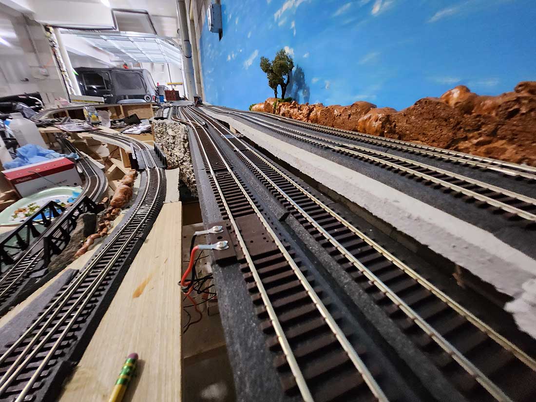
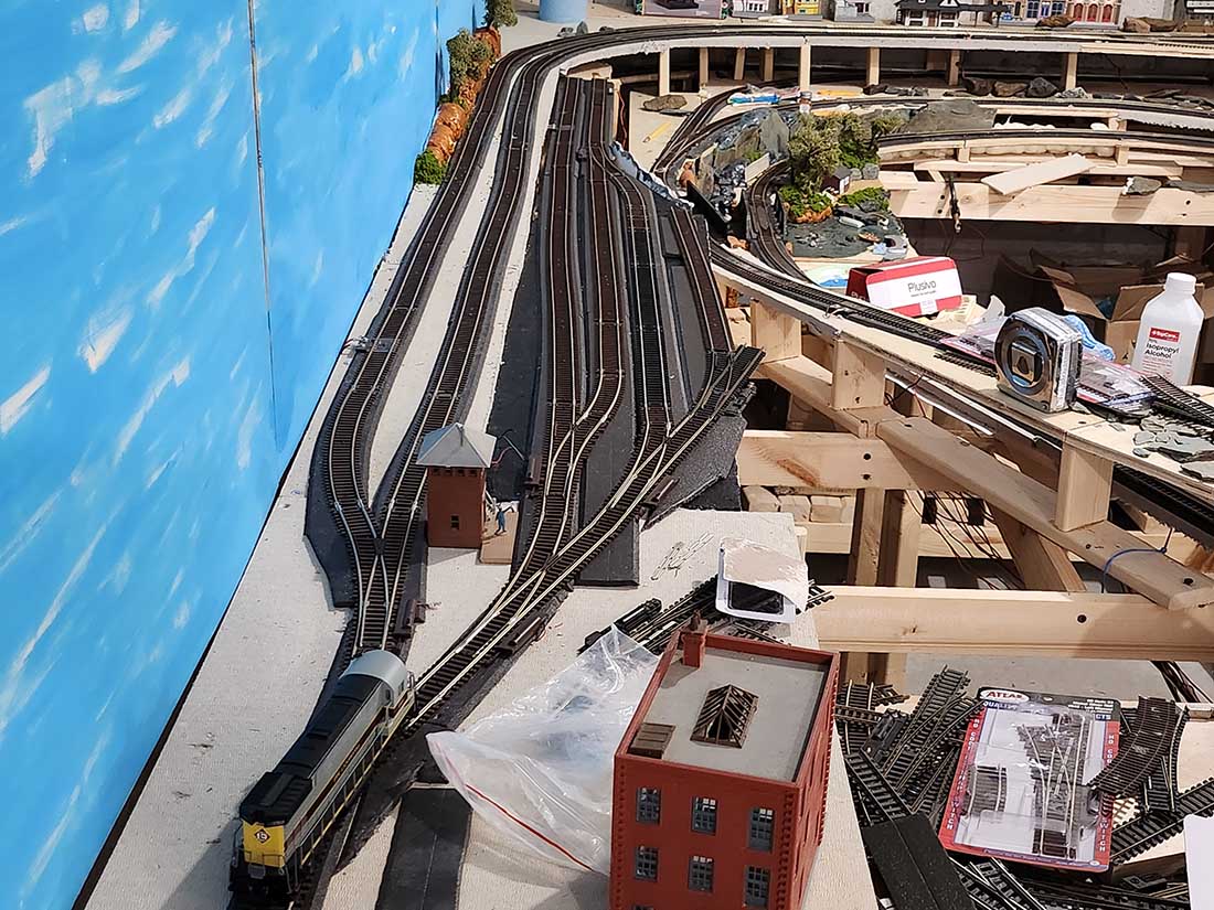
I heeded the advice of some readers who commented on my original post: “start adding a backdrop to the layout!” I concentrated on the longest stretch of the layout first — the double-track main line straightaway between Gregson and the curve leading to Highlands.
I have kept it simple — blue sky and clouds. I used three, 2’x4′ sheets of 1/4′ blondewood plywood to cover that stretch.
I painted the white side of the plywood using three shades of acrylic Cerulean Blue paint, with the darker shade at the top that progressed downward to the lightest shade at the bottom. This was a suggestion from the artist in the family, my wife, Mary Ann. I spread the blue paint unevenly across the plywood, leaving patches of white — representing clouds — along the way.
I mounted the plywood directly on the room’s cinder block walls using outdoor-grade velcro strips that adhere to the cinder block. It has worked out fairly well and I plan to use this same method for the rest of my backdrop needs.
Getting that strip of backdrop in place was critical to starting work on one of the two remaining major unfinished portions of the layout — the main freight yard at Gregson. It is being named Croxton Yard after the real former Erie-Lackawanna freight yard in the meadowlands in Jersey City, NJ, which is a few miles west of Hoboken.
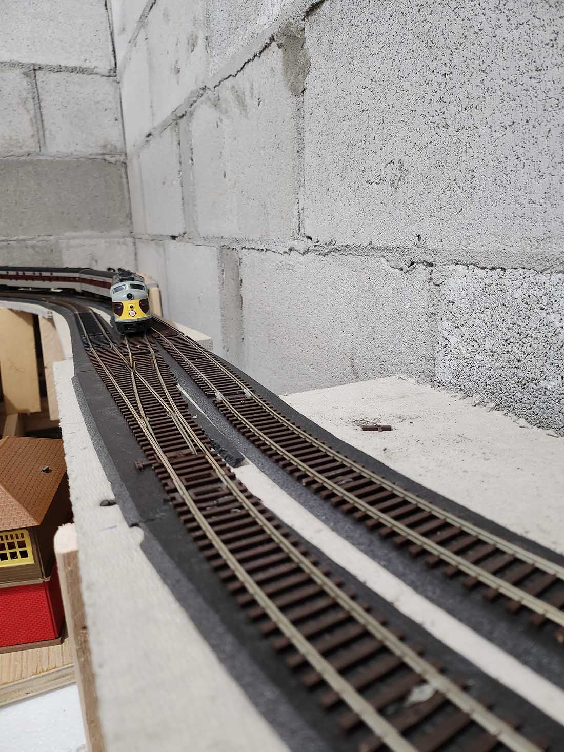
I am trying a different construction approach for the subroadbed for Croxton Yard. I am laying a 1/4″ strip of styrofoam on top of a 1/4″ strip of plywood on which the track and roadbed sit.
The idea came from a television program on the National Geographic Channel regarding the renovation of a major train station (I believe it is in London). The tracks and passenger platforms sit atop a series of historic, arched underground passageways through which travelers walk.
Apparently there were structural integrity concerns due to the age of the station. So, to support the platforms and tracks above and protect the passageways below, a layer of styrene and a layer of concrete were installed below the tracks and platforms. Styrene, while lightweight, apparently provides a very strong cushion for the concrete. My thought was: “well, if it is good enough for a real railroad then why not try it on my miniature one!”
I had saved “for a rainy day” several large sheets of styrofoam of various thicknesses that were used as packing materials for outdoor furniture we had ordered. These were perfect for what I had in mind (for once, my pack-rat ways paid off!).
I already had tried using styrofoam on a small section of track in the Marysville area — sandwiched between two layers of plywood — and it provided the needed support.
For Croxton Yard, I flip-flopped things and put the plywood underneath so that I could screw it into the support piers and then glue the styrofoam on top of the plywood. I painted the styrofoam black because, from my observations, the ground in between tracks in yards and passenger terminals seem to be a very grimy dark color.
I can add on later some details like discarded items normally found in yard areas, weeds, etc.
So far, the combination of styrofoam on top of 1/4″ plywood seems to be working. I’ve laid down tracks (code 83 like the rest of the layout) and turnouts (mostly #4 Atlas snap switches and some Atlas 22-inch radius switches) on the portion of the yard that is furthest away from the edge of the layout.
This allows me to continue using an access hole so that I can finish putting in scenery in Gregson that I can’t reach from the edge of the layout. Track nails penetrate the styrofoam very easily and thus far don’t seem to be popping up. I will use this method to finish off the yard.
At this point, I only have room enough for five tracks in the yard. It is a stub-end yard but two of the tracks can serve as runaround tracks so there is plenty of flexibility for yard switching operations. And two of the tracks are at least five-feet-long so the entire yard should be able to accommodate 30-40 cars.
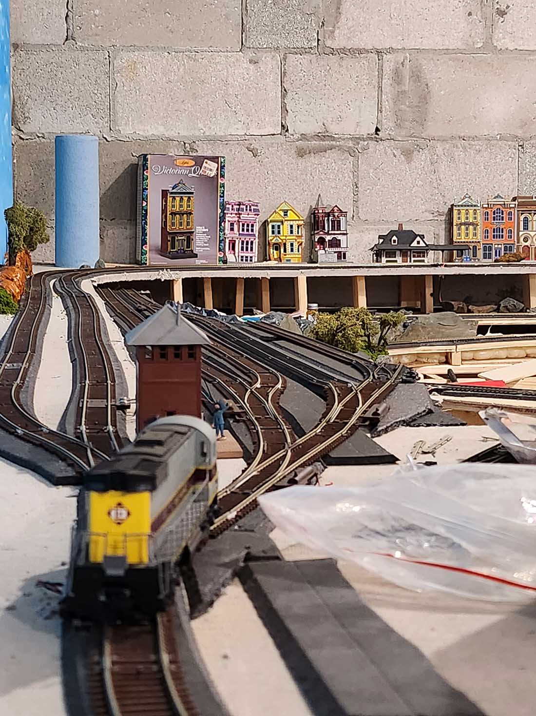
Work also has begun on the Hoboken area, which is the other unfinished major piece of the layout.
I laid down several pieces of Oriented Strand Board (OSB), which is used as subflooring, to cover the approximately eight-foot by three-foot area that will house the Erie-Lackawanna passenger terminal tracks, yard and a highly compressed version of the City of Hoboken.
OSB is an inexpensive option to standard plywood. The OSB is elevated three and a half inches above the benchwork to allow for the branchline to loop underneath it.
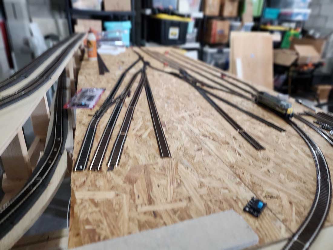
At this point, I am laying down track temporarily to figure out the layout of the yard. What you see in the photos is likely pretty close to what the final track configuration will be.
That big open area at the middle-back of the yard will house a diesel fueling facility.
The long track on the far right in the photo looking away from Hoboken will serve a Commissary/Freight building for servicing dining cars, and a Railway Express Agency terminal. The other tracks will be used for passenger car storage and staging.
One thing I will do before getting the track down permanently is to cover the OSB with sheets of 60-grade coarse sandpaper, which I think simulates a gravelly surface fairly well.
Backdrop
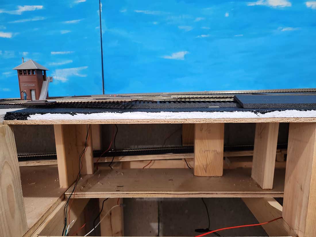
Cross section of Croxton Yard
Croxton Yard
Croxton Yard
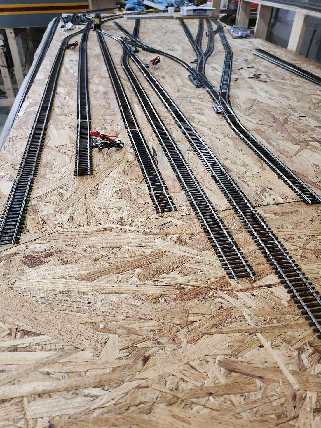
Hobroken Yard and terminal looking away from Hoboken
Hobek Yard and terminal tracks
New mainline crossover
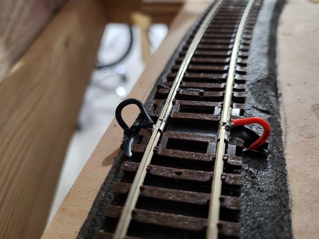
Solderless electric block connection at Verose Valley
That’s it for now. Obviously, there is still a ton of work to do. Hopefully, I will have made some real headway with scenery and in finishing off the trackwork at Croxton Yard and Hoboken when I provide my next update.
Jersey Shore John”
A huge big thank you to John for sharing his Erie Lackawanna model railroad update with us.
If you missed his previous post, it’s here: HO scale track layout
Very much looking forward to seeing how this one progresses!
That’s all for today folks.
Please do keep ’em coming.
And if today is the day you stop dreaming and start doing, the Beginner’s Guide is here.
Best
Al
PS More HO scale train layouts here if that’s your thing.

the passenger train is awesome & the way he is building the rails were they way above or below the others is interesting to me. one day, I will have my trains set out to do what this man is doing. great work.
John,
Great play-by-play of the building of your layout, hope to get more news as your work continues. Man-I love those long straight-aways, sure wish I had room to do the same.
Thanks,
John from Baltimore
From these pictures what a huge difference a backdrop makes, even if it is a plain sky backdrop.
Jersey Shore John
What a fabulous missive. You made quite an effort to compose this very honest and informative piece and I for one thank you profusely.
In modelling there is the key adage: ” Dont be afraid! “. If you model you must solder and if you take the advice of someone who learned the hard way, and finally took the advice of experts, I have the best unit for me. Circuit Specialties is a great company, stands by their stuff, expert assistance and has a 60W station for less than $50. Get it, solder those wires and tuck them away, and you’ll thank me forever. Get a bottle of liquid flux from Micro Mark ( a little goes a long way) and some electronic solder and you’ll be a wiz in no time. Throw out those Weller pieces of junk and you’ll be fixing tiny wire joints like a pro. I put many hours on mine and now cant be without it.
Please send pics of the control panel, especially the back, and keep us posted on updates.
Big Al
Gracias Amigo
Jersey Shore John:
Great narrative and lots of good info. Great work so far. Send pics as you progress.
.
A big THANK YOU to Jersey Shore John for an excellent account of his modelling to date. Keep it up and I look forward to receiving more updates in the future.
As to soldering – I had and still have issues but each time I get a little better. Like riding a bike – it will come
Thanks again and best wishes to all.
Andrew in Oz
I worked many years out of croxton.if you need any input I’d be happy to help
Wow what a narrative … most impressive , you are determined indeed . Great theme , looks like it’ll be superb. Good to have so much room , please keep oaring your progress .
really good layout. i like it.
Really curious as to where you got your “Blonde “plywood with the painted surface you used in your background scenes. Also, where you got the Outdoor velcro that will stick to cinderblock surfaces.
Thanks in advance, Dover Bill
What you’ve done so far looks great. Keep up the good work. Rob
That looks like a very ambitious and interesting project you’ve undertaken John. You’re certainly making good progress and learning by doing. I was a bit surprised to see you wiring the layout as straight DC block control in this age of DCC and microelectronics, but it was good enough for many of the greatest model railroaders I knew. Keep up the good work and let us see some trains running on it in the future.