Gerry’s been in touch with a problem he’s been having with his HO scale feeder to bus wire.
Happily, you lovely lot have rallied, and if you are having the same proble with your wiring, look at all the answers and comments below.
“Hi Al,
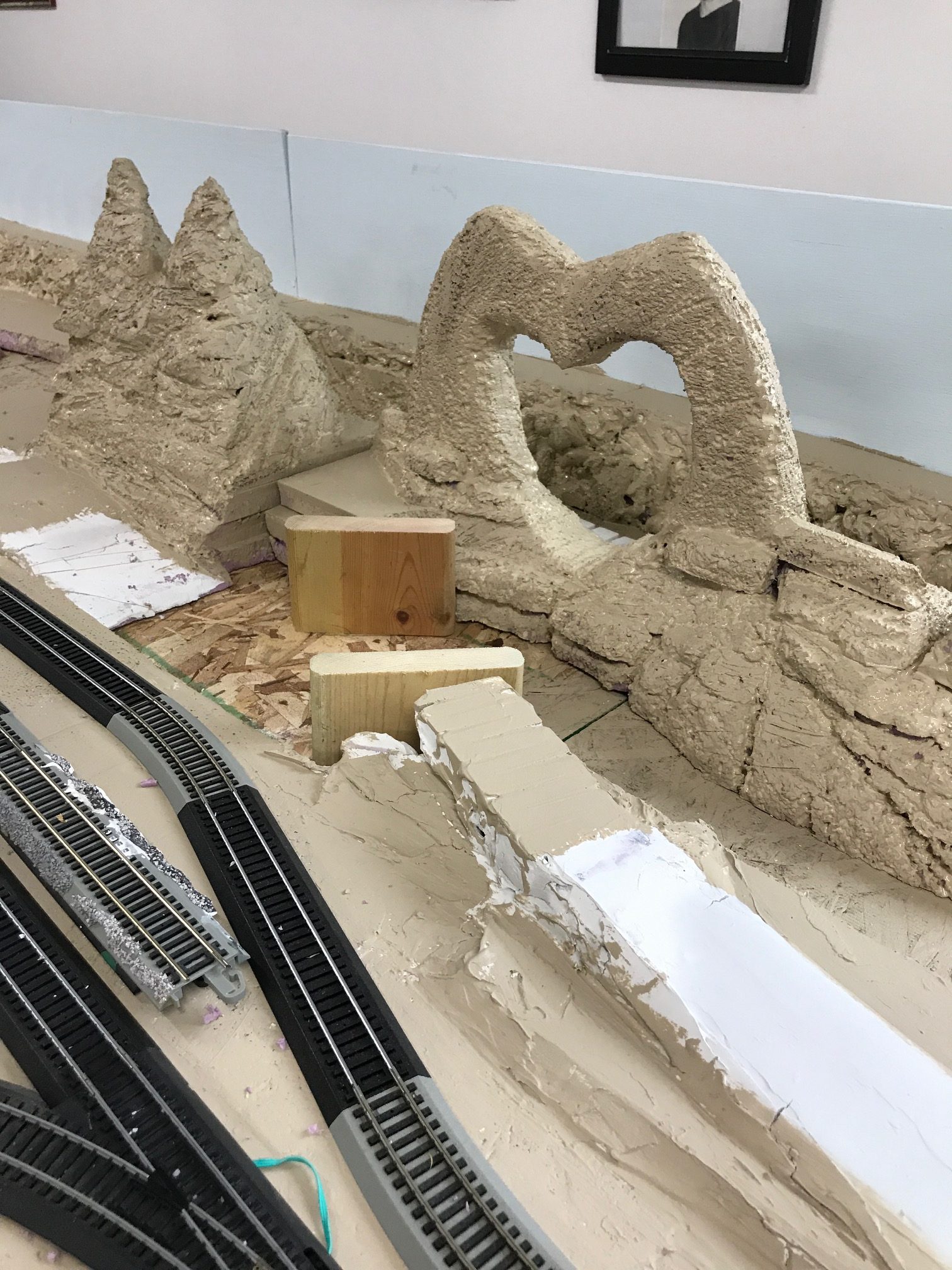
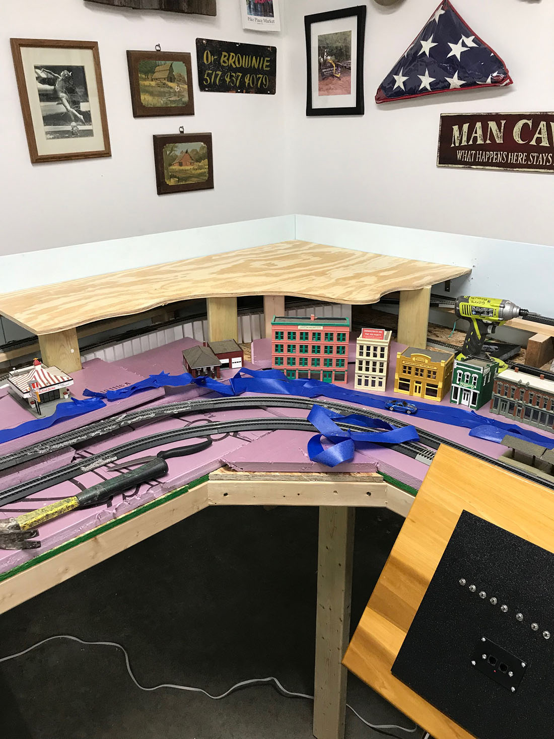
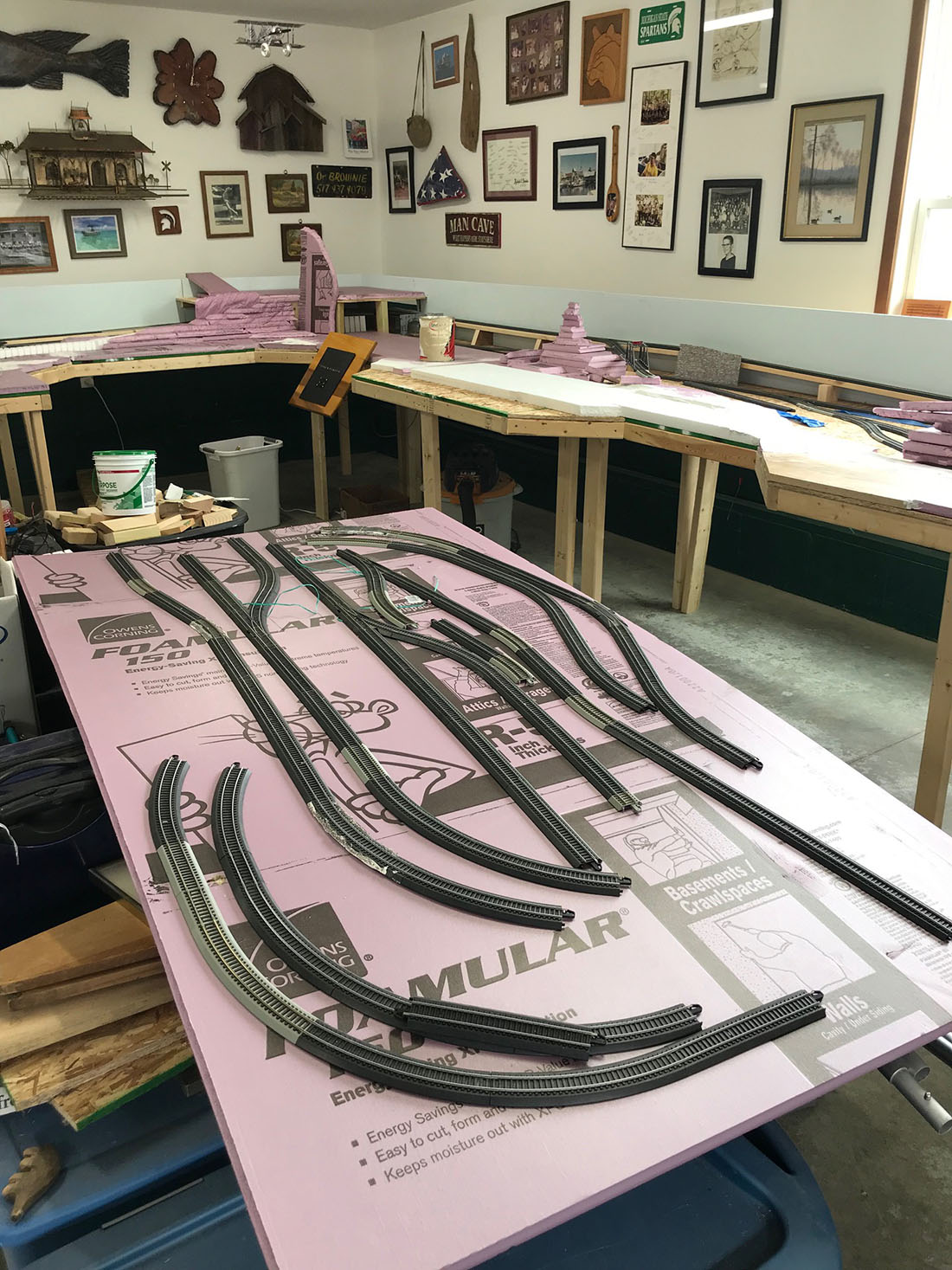
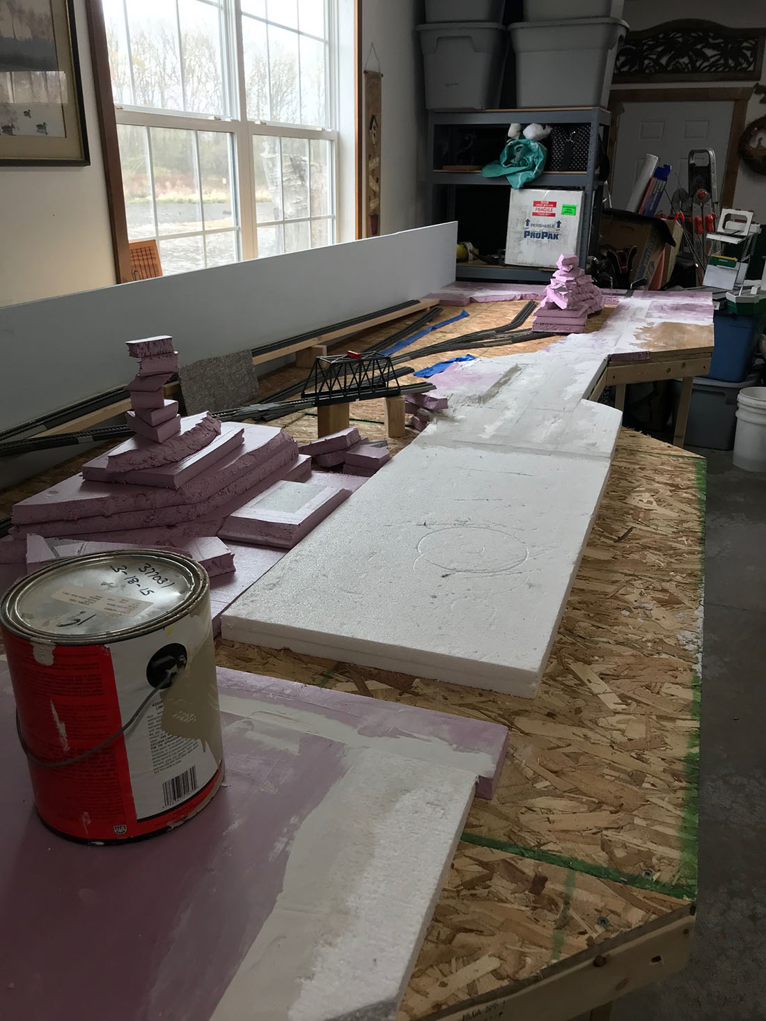
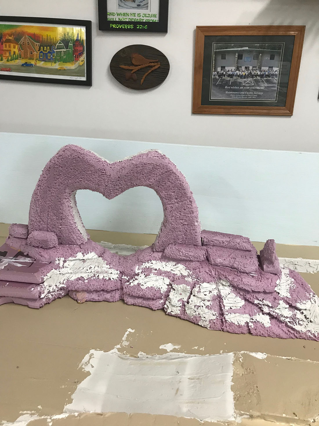
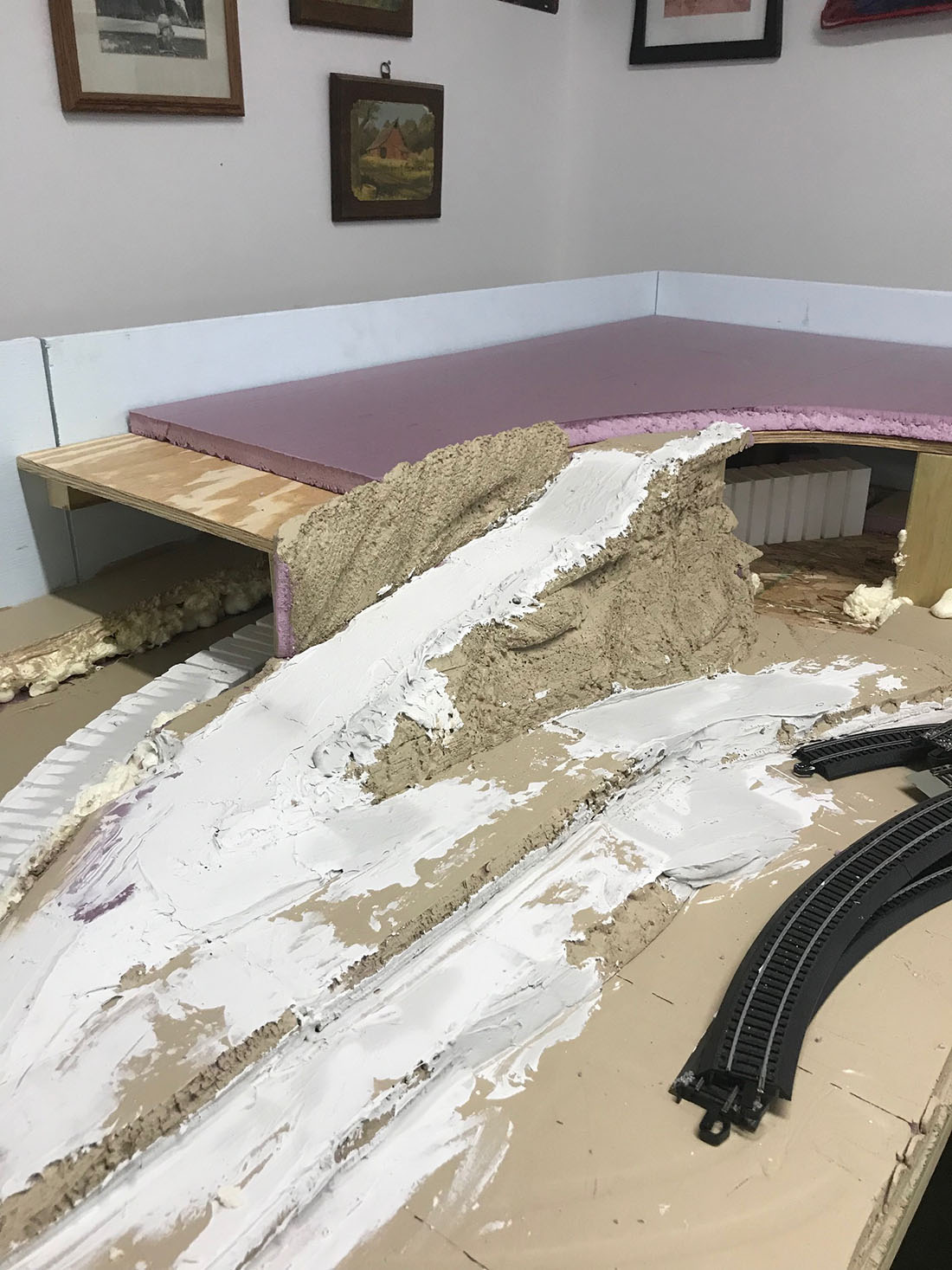
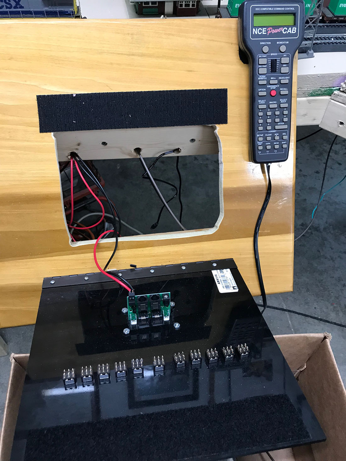
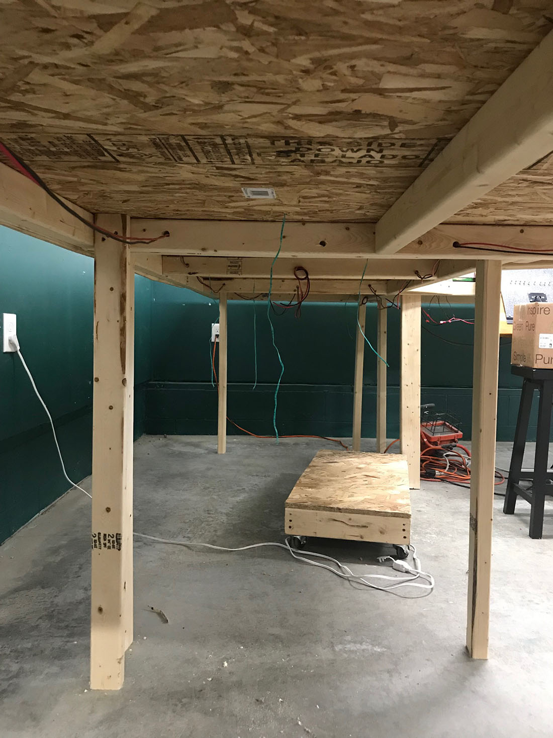
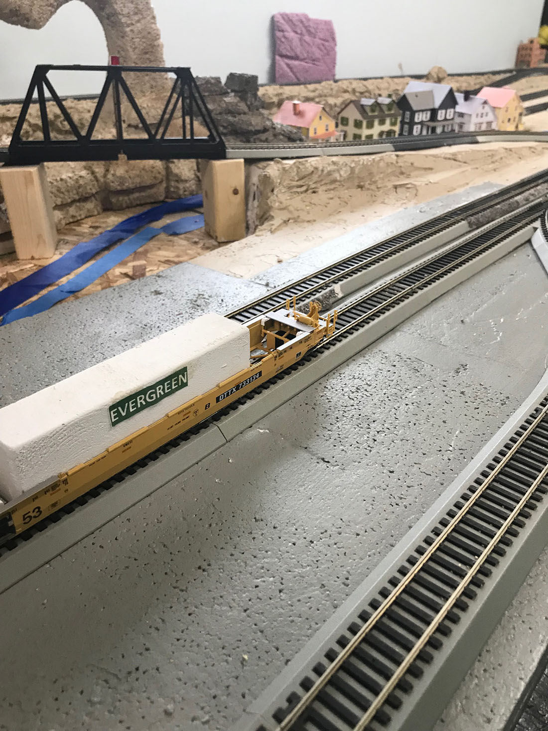
I have been slowly building a new HO layout which is just now ready for electronics work as all base painting and landscaping is done.
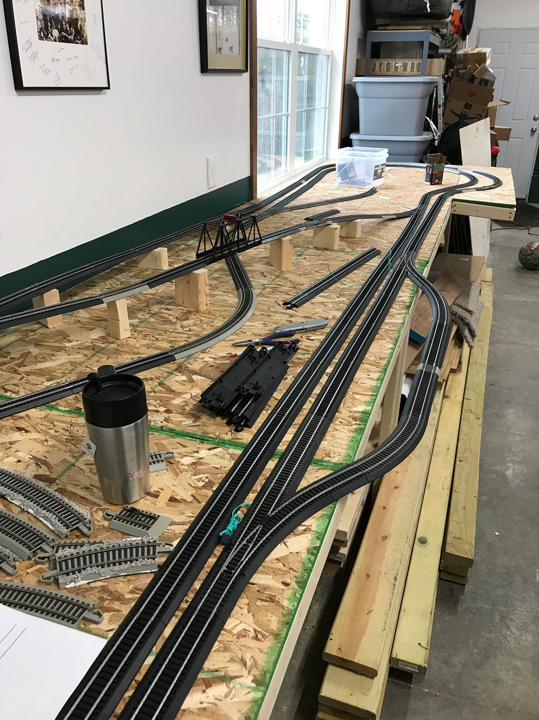
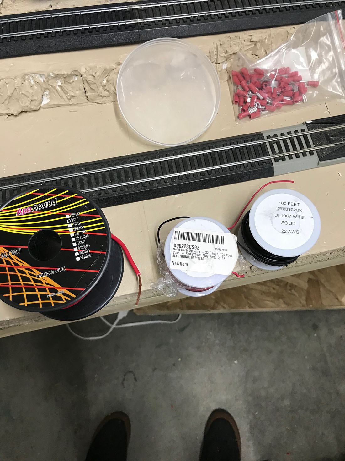
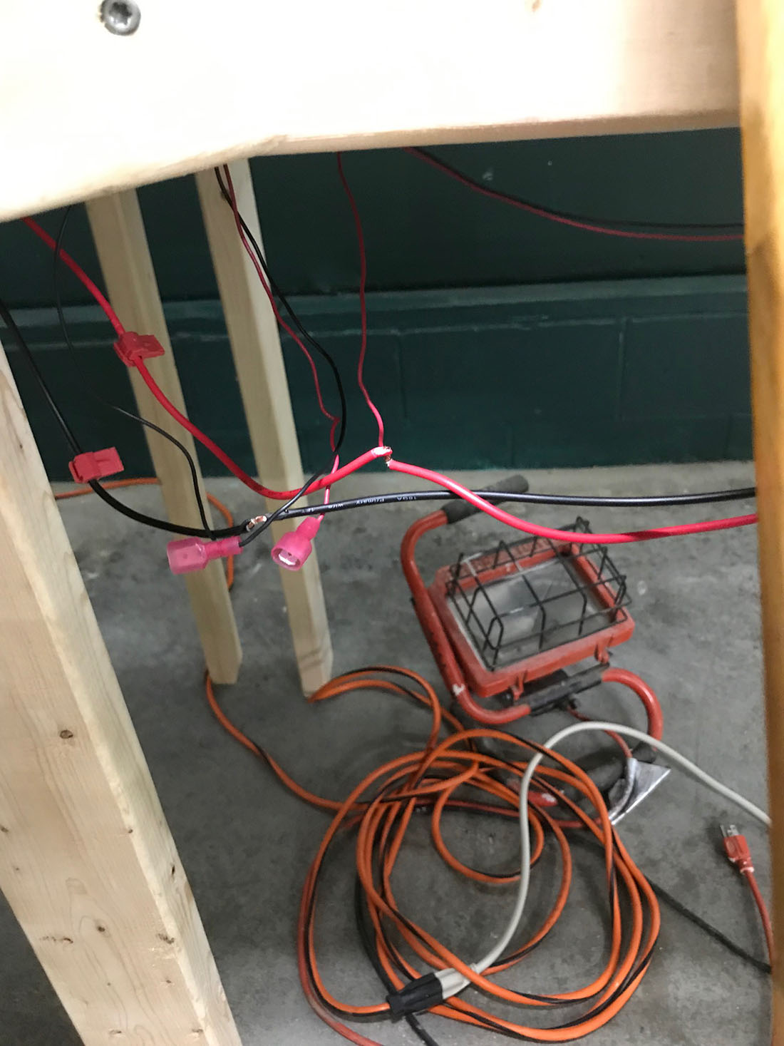
But big problem as my first attempt to attach feeder wires off a bus line has resulted in cross circuits. Need help!!!
So need to get locomotives running before doing detail work on every square inch ovt next 10 years…
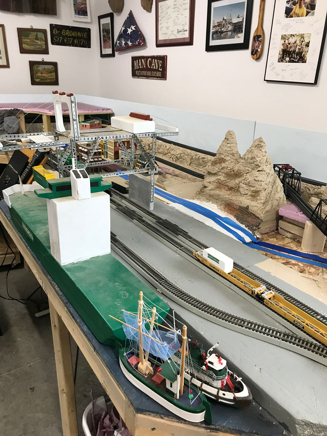
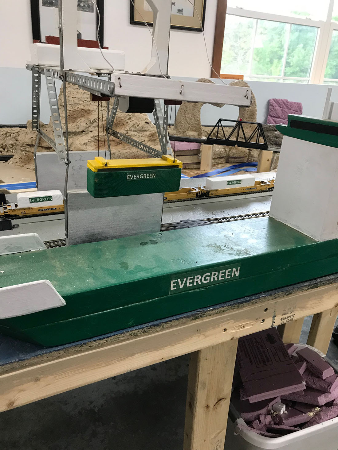
Had just 2 inches to spare to get boat in the garage and close the door…!
Thank you AL for your blog as I really enjoy it and Johns paper buildings keep me busy in winter as we return to Florida for winters.
Thanks.
Gerry.”
A huge thanks to Gerry – looks like he’s having fun. But who can help him that HO scale feeder to bus wire issue?
Please leave a comment below if you can point Gerry in the right direction.
It reminded me of John’s post:
The comments and suggestions on the bottom of that post are very helpful too – if it’s something that you’ve been scratching your head over, it’s worth a read.
And there’s also Lawrence’s post too:
Also, Barry’s post is helpful:
Barry explains wiring for your model railroad.
Remember, it’s the comments that hold just as much advice as the posts.
That’s all for today folks.
Please do keep ’em coming.
And if you want to your start, on your very own layout, the Beginner’s Guide is here.
Best
Al
PS Latest ebay cheat sheet is here.
PPS More HO scale layouts here if that’s your thing.


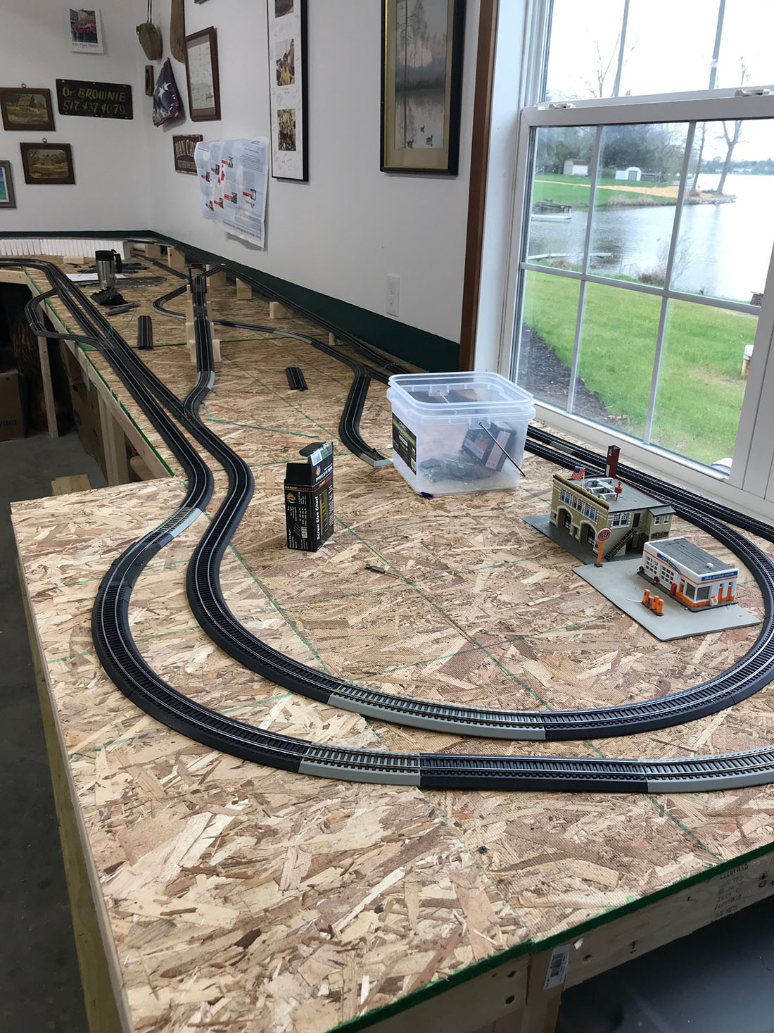
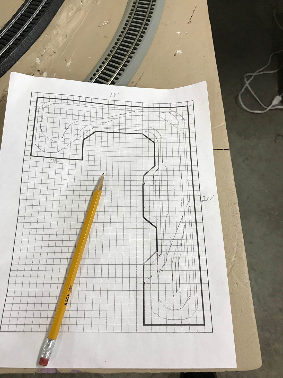
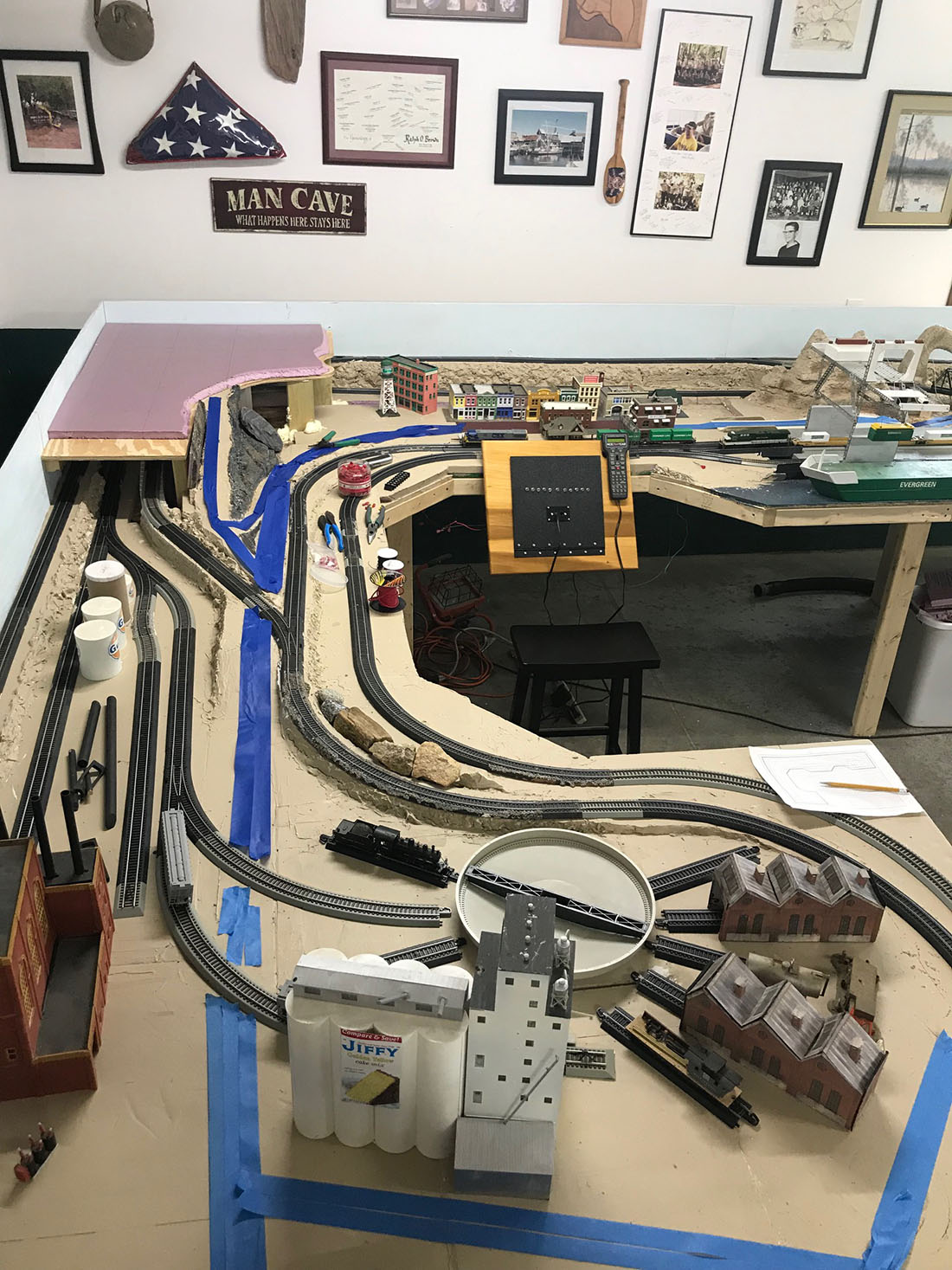
Could the short be caused by the diagonal connections (track connecting one side of the loop with the other)?
I’m no expert, but looking at the track diagramme, and the layout itself, it might be the track that crosses the layout over the double bridge that’s the issue. It means the inner supply rail at the start of the section meets the outer supply rail at the other end, resulting in a short circuit.
Hi Gerry,
Looks like you have a layout with 2 rail DC or DCC. If there is any place where your loco can turn around and it is not a turn table, you are guaranteed to get problems . (Think for example of a cross over to the other side of the layout) If you really need that, you need to isolate that part of the layout and use a specific turnaround module for that part. But iti woud be better to completely skip such a part in the layout.
If this is not the case. disconnect all feeders but one. Then the loco should be able to run at that part of the layout. Next, connect the feeders one by one and each time check if the loco still runs. If not, there is a problem with the last feeder you reconnected. Beware of switching the wires. Happened to me too often.
Regards,
Ruud
Gerry, I noticed that you have RED on left rail in both directions. Possibly one track should be the other way around? start removing sections of track wiring until the fault clears
Gerry, Hmm let me try again……It appears that you have RED wire connected to RIGHT HAND rail on both tracks…Perhaps one track should be the other way around?
Start removing sections of wiring until the fault clears, then you know where it is.
I think it’s pretty simple. On the right hand side
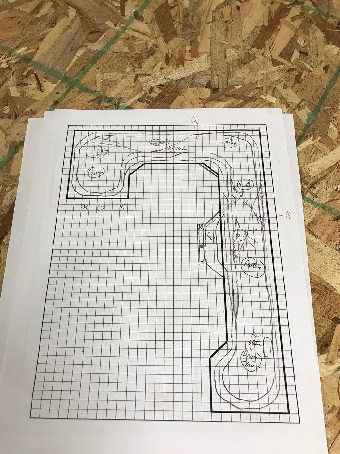
Below the figure 20 there are two problems one main line and one to the sidings. Basically there are two return loops where the power short circuits.
Check out a website called Brian lambert and you will see the problem explained in perfect detail.
I had a similar issue myself and couldn’t see it
Once explained it was very clear.
Gerry, I note you are using dcc. Good. But you will likely have a “phase” issue. DC has polarity but DCC has a phase issue that can cause a short circuit. In plain language you have your black and red wires joined together somewhere? A quick way without the power on the tracks, is to use a Digital Multi meter with a buzzer built in. Put the probes on each track and it should stay silent. If it buzzes then your wires are back to front. You may have to break your layout up into sections (electrically speaking) to make the job easier.
I note you have two reverse sections. They must have an auto reversed fitted, otherwise you will have a dead short. Probably a good idea to disconnect those two before you start.
I hope the above helps, good luck
Pete
Gerry,
The others have answered your problem well.
The easiest way to visualise this problem and to test for it is take any wagon and put a piece of red tape on one side and black tape on the other. Now put it on your layout.
Make a note of which side faces you.
Now run it round your layout and in each track section you reach just pop a bit of red tape down on the same side as the red tape on the wagon.
Once you have been through every section of your ovals, now continue and take it through the crossovers.
The wagon may now find itself on sections of the oval with the black and red sides reversed. Hence the short circuits.
So you can tell instantly by looking at the wagon if the wrong colour has appeared in a section. The point at which this happens is where you need to cut the rails and put in insulated joints. You then put a polarity reversing control board in at that point.
To see how to do this PECO do a handy little guide called wiring the layout which shows exactly this “reversing loop” problem.
As a few have pointed out, if you really don’t need to cross from one side of the layout to the other then take them out and simplify your life!
Hope this helps.
Mal
North Wales.
It is fixed….! The wagon idea worked perfectly and yes the inside loop and outside loop feeder wires had to be reversed. Thank you so much….! Note:
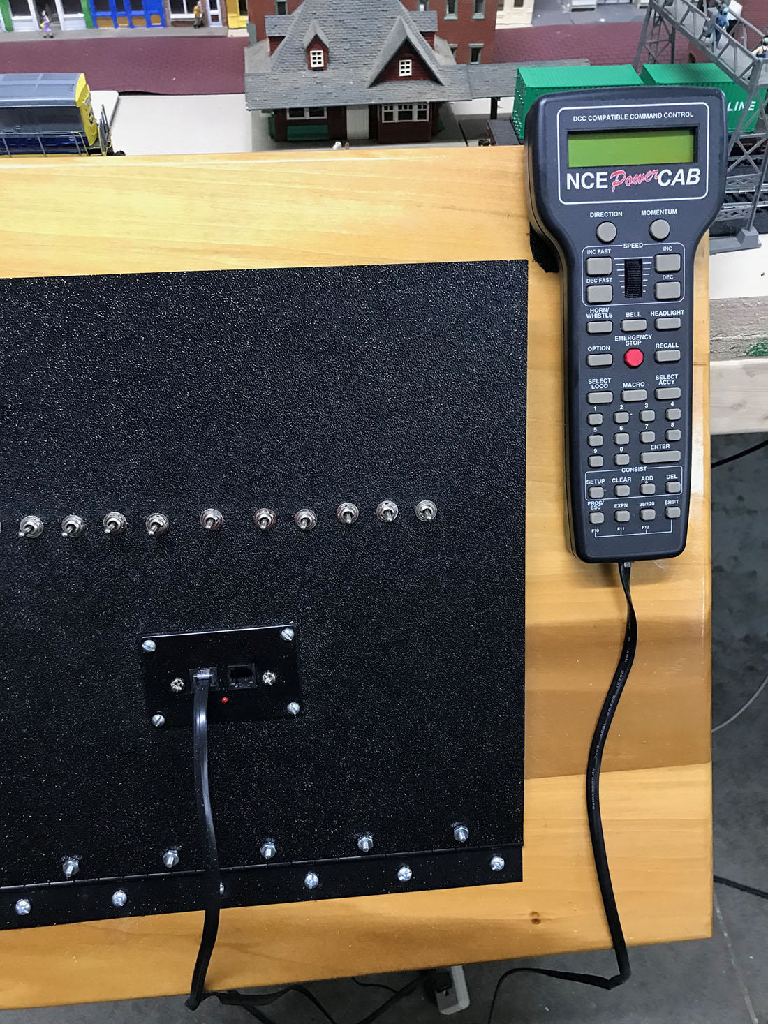
There are no reversing loops as both cross overs go in same direction. Unfortunately the engines still did not work but a quick call to NCE and with Ed’s help I was able to get 1 engine coded correctly and it worked perfectly on first time around!!! I have gotten much better at welding feeder wires every 3 feet and using snap connectors so I am really really happy about that. But, My other 2 engines were not able to get coded so may need to get need new coders installed??? Very disappointing. But making major head way and appreciate everyone’s help. Gerry
Gerry,
Mr. Coleman cited Brian Lambert web page.
Google search Brian Lambert wiring problem.
Nice layout.
Hope you resolve the problem hastily.
Bruce in SC USA
There may be a short circuit at the area marked airport and another at the area marked port on the track plan drawing. they appear to be crossovers that will reverse direction of travel. If so, they will need to be isolated and have a reversing switch inserted if you have analog (DC) control , or a reversing module if DCC.
Gerry,
It looks like a reverse loop where the track runs across at your wife’s heritage park. You’ll have to read up on this. Methods vary for DC Vs DCC.
I would put money on the cross overs. That’s where mine was I like the idea of the tape on the car it would have made it easier for me to find mine. Good luck
Gerry, Best to you in the process as it is great to view from here. I am learning more thanks to your post and the replies. I initially felt the use of a multimeter is going to solve any issues for me forward. That was going to be my suggestion is to get familiar with a multimeter (I’m still trying after a few years). Thank you for sharing this and thanks to the responders.
Looking at your track plan looks like you have reverse loops and if you do there is your problem.Reverse looks take special wiring. I have a MRC and runs really great with no problem. Ron sunny Florida.
Mal, the idea of black tape/red tape is brilliant!
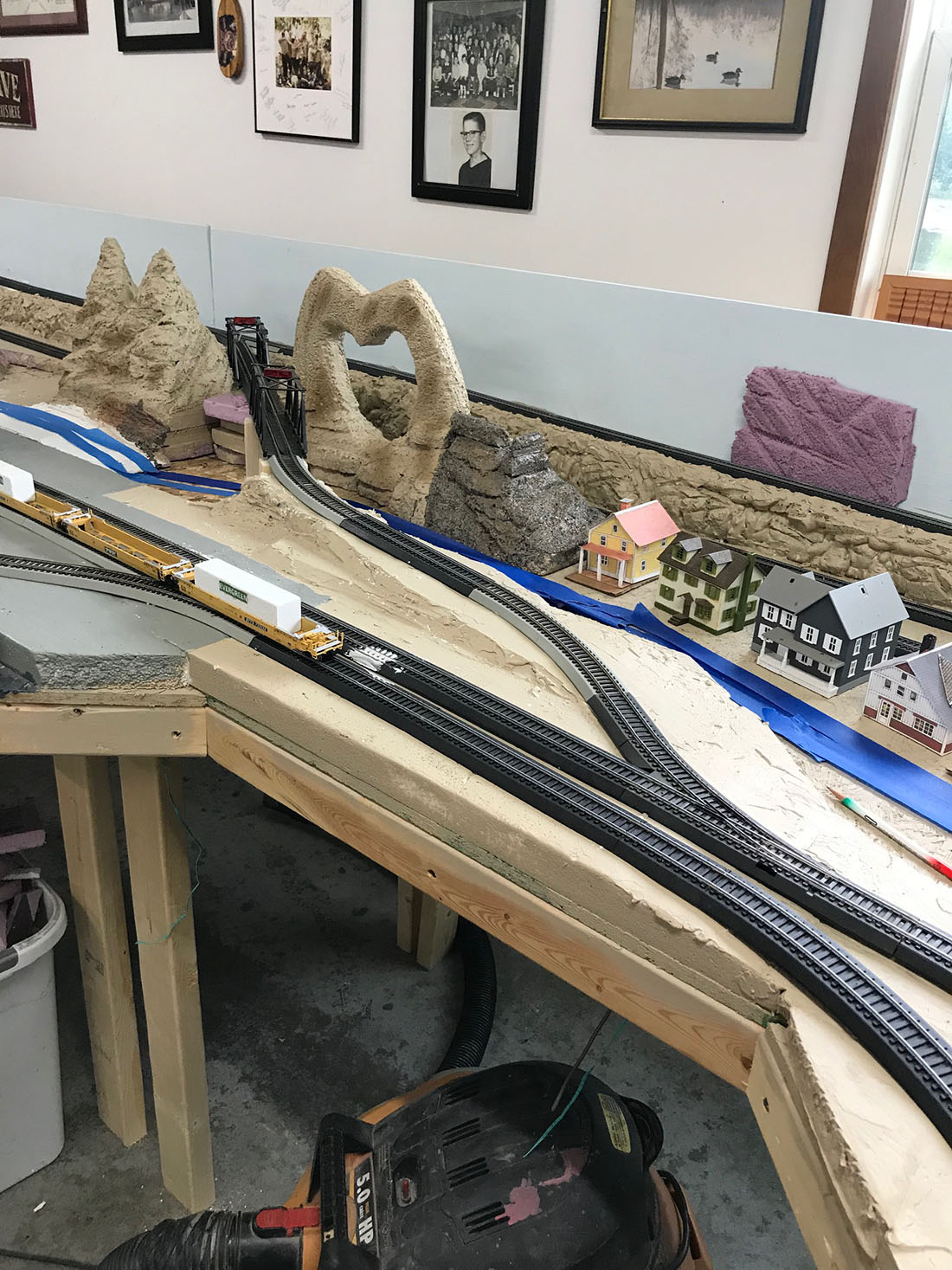
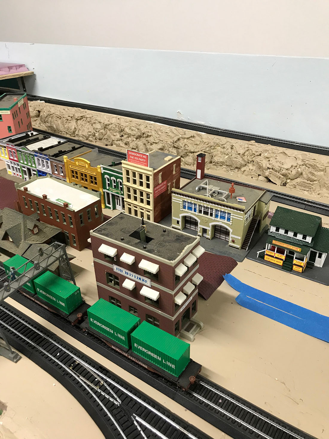
Well, good to see you’ve got the wiring issue resolved. But it’s great to see the progression of your layout coming to life. Great space and size for detailing scenes and scenery. Good start. Thanks for sharing.
Jim AZ
Gerry: I say it’s the bachmann lighted tressel bridges causing the short they’re DC One of my 2 was giving me a problem ,took it apart and built again and works.
Gerry, glad you found your wiring problem and it was easily fixed. About your two decoders that won’t work. … who installed them? If it wasn’t you, I would contact who did, and see if they will take a look at them for you or swap them out. If you did them, the two main problems could be 1)a pinched wire between the decoder and the loco, or … 2) the same problem you had with the layout, two wires hooked up in reverse. Hope this helps. Fun layout!
Lee
Gary, your cross over is creating a double return loop. which is shorting your system. Also, at the end of the layout (the short leg) it looks like you have created another reverse loop on the inside track.
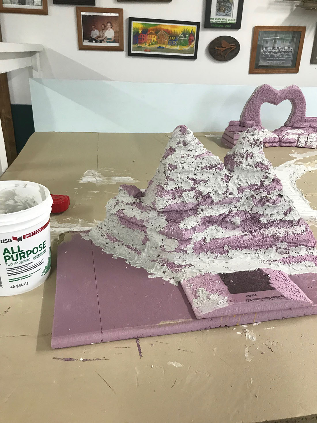
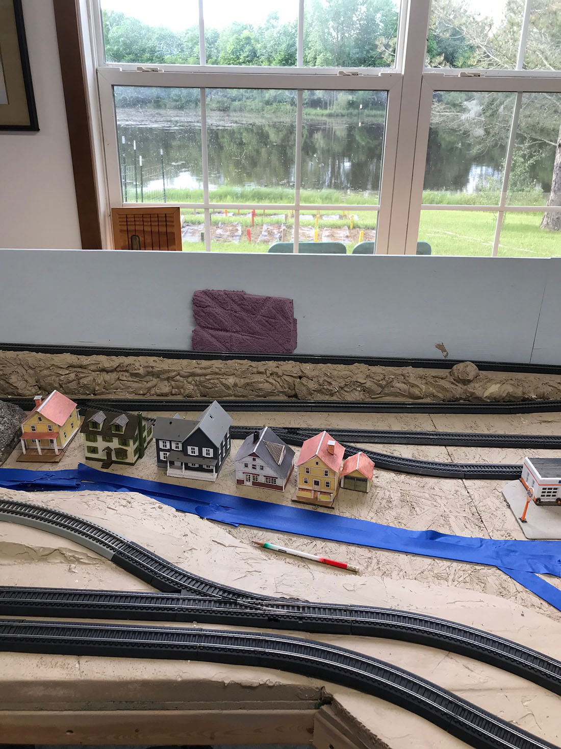
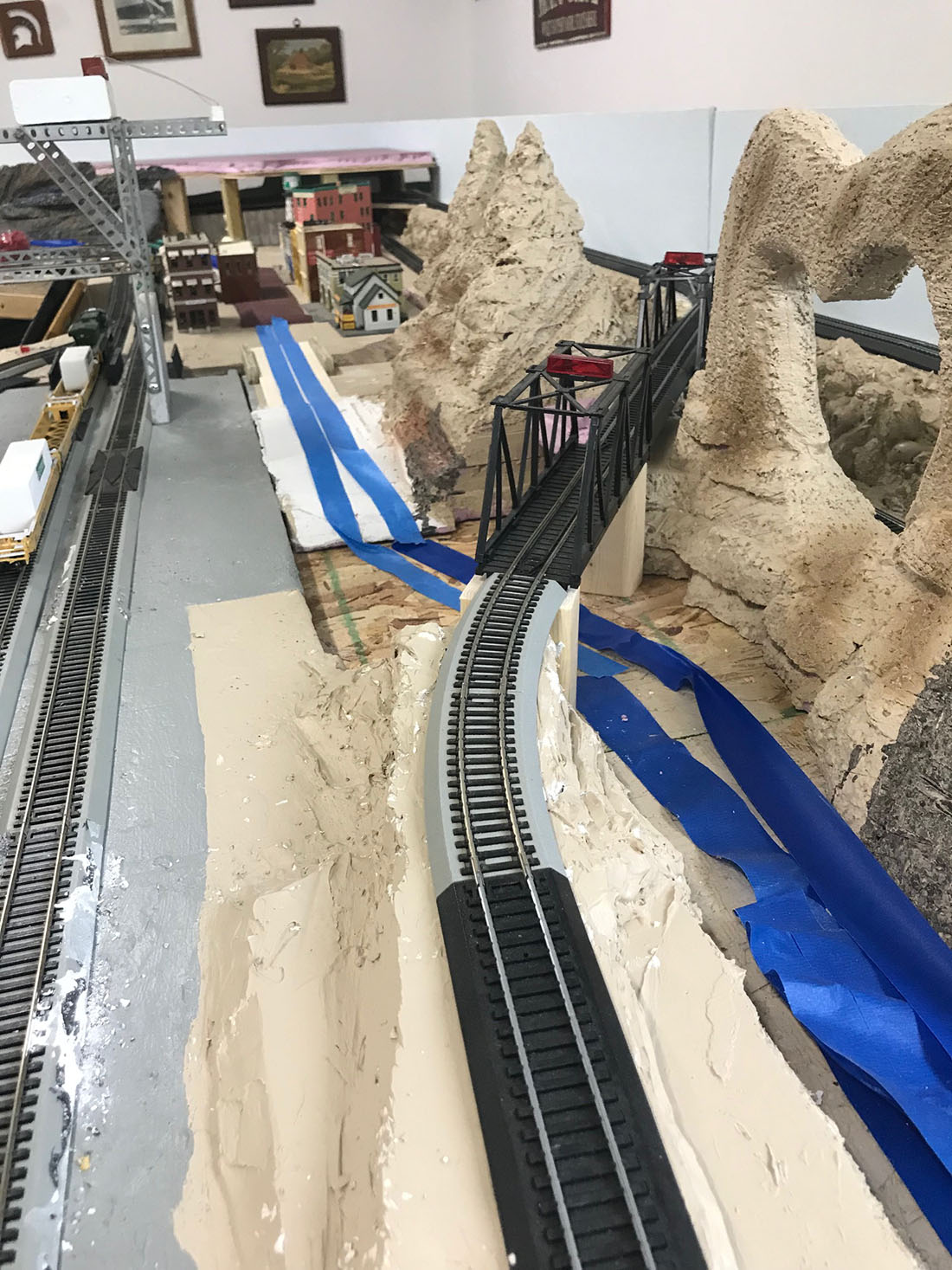
You’ve got a wicked “S” curve across from that piece of square pink stone on the wall. Substitute a left hand turnout for the right hand one and you’ll see a big improvement. If you need to have an “S” curve, you should have a straight length equal to your longest car between the turnouts.
Gerry, Be encouraged, your layout is coming together beautifully and there are always going to be a few glitches! Keep on keeping on. Toot Toot! Jeff in Seattle
Gerry you have at least one crossover track going from one side of your layout to the other, as others have said that is your problem. As a quick test remove completely one piece of track completely from each crossover that should eliminate the short circuit, unless you have wired it incorrectly elsewhere of course !!!
Cheers Mike S
You need insulating joiners or just gaps in these sections of track and Reverse Loop Modules to automatically switch the current on these crossovers when a loco goes over them.
Looking at your track plan you have three reverse loop.
Easy fix since you are running dcc. Insulated joiners at each one of the three crosses. Ar1 wired to those three and back in business!
Gerry and All, I recently moved from dc to dcc, but left the ‘blocks’ intact. I still run in either mode from day-to-day. If I ever build another layout, IT WILL BE IN BLOCKS regardless of what mode I want to run. Much easier to fault find.
You will need an AR1 DIGGI Trax Module 9Automatic polarity control) where each cross-over and diamond crossing is there will be a wiring diagram with each one to change the polarity for each time the loco uses them
Once you have disconnected your feeders one by one, or preferably before, check that there are no cars or locomotives sitting on a turnout that is inadvertently switched the wrong way. This one is the most common cause of shorts for me over the years. I am not sure how the turnouts wind up wrong but they do. It usually happens when I come back to the layout the next day or after some period of not being used. Best of luck, those shorts can drive you crazy. One of the best ways to control them is to have multiple sections of track you can switch in or out of the system. That way you can locate the short to a smaller area instead of the entire layout. Rob McCrain – Farland Howe
I have two turn around loops one at each end and I had to install 2 reversing loop modules cause the + gets switched to other rail on the loop. Read up on reversing loops and you will be ok.At a quick glance of your diagram Label the left rail as + and once it gets to the straight away you will notice the + is on the opposite side.Hope that helps Cheers Brent
It looks like you have a great start on your long-term project. I especially like the Erector Set gantry crane for dealing with the ship cargo.
What can I say that others have already said? I loved your crane idea, how original and unique. I love it when ppl think outside the box. I love your layout and I am impressed with your innovations, keep up the great work!
That’s kool!!!!! I hope mine turns out that goods.
Very nice start. looks like it’s going to be awesome.
Just a note on inspection cars; You can make your own very easily. I used an old “skeleton” logging car I broke off he outrigger’s and installed a good pair of trucks. Now you do not even have look thru clear plastic to see what is going on down there. You don’t need an old car; you can use a piece of narrow tubing or flat bar to mount your trucks (and couplers if you so desire). Mount things true with appropriate wheelbase for the equipment you have and weight it properly. Mark one side red and one side black. Now, you not only have a nifty inspection car, you can use it to drop feeders using it, you can use it to check your wiring when it is done by rolling it around every conceivable route and look to see if you get the red side of the car to the black side of the wiring
I like the stone work. Reminds me of Star Trek. The “Edith Keeler” episode.
I’m not up on electronics, but I like the track layout and your bench work.
It should come together nicely one day.
Frank in Orlando
Short circuits! I have been there, so you have my sympathy! As suggested above, disconnect each feeder one at a time until you find the issue. It took me ages with wiring looking like a bird’s nest!!!!