John has been in touch with how to put together the infrared detectors for model trains.
“Hi Al,
It’s been awhile, been busy working on some real railroads since many of the folks who normally do the work are locked down and can’t travel, but I’ve been reading the posts every day.
Your website and the products you offer are great for any level of model railroading.
Now to my latest project. I’ve been trying to get some way to detect trains as they pass, and drop signals to red when they go by.
There are some good detectors out there, but I wanted to see what I could figure out on my own.
I’ve been fooling around with the little sensors used in manufacturing mostly made to send a signal for something, like light being on, or to turn on lights when dark, or objects passing by on an assembly line.
How about people sensors? Both types had some utility, but the turn on the lights did just that, but not when I wanted to run trains.
The people sensors… well… sensed people, not HO trains, and when I adjusted the sensitivity they detected everything but trains.
Back to research, and success!
I found little IR detectors on eBay for less than $2.00 each. A lot less than that from China (just ordered 20 more for a total of $10.33!) but it takes a few months mail, and customs, and red tape to get here from there.
They are called Arduino PIC AVR IR Infrared Obstacle Avoidance Sensor Module Object Detector.
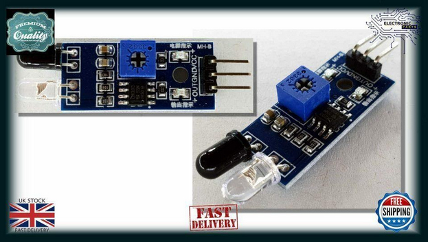
Size is about 16 mm by 50mm with a plug attached. They run on 3.3 to 5 volts DC, and will detect anything directly in front of the sensor diodes.
Out of the package, they will detect from a little as 8 mm and, with playing with the potentiometer, out to about 40 mm.
They react fast, and in a few tests actually picked up the space between the cars. Not good. So I decided I would modify the detector, but quickly determined that connecting everything with jumpers and alligator clips was tedious and confusing.
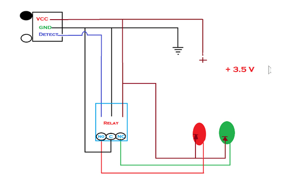
So I made a little test board. It has a place to connect my power supply, a common cathode type “D” 2 color signal, and a relay to get the trigger from the detector and change the signal. I use a relay, also from eBay, 1 Channel Relay Module 5V Optocoupler LED for Arduino Pic ARM AVR note that it has the same plug as the detectors. This is a single pole – double throw relay that would work with the same voltage as the little detectors.
Since I’m planning on having a dozen or so of these detector/relay/signal sets, I also bought some 3 conductor connector sets that plug into the board and relay.
The circuit design is:
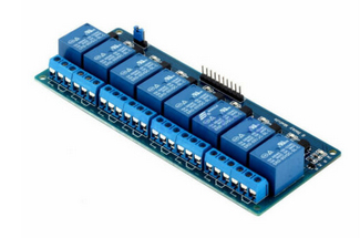
I found that the relay below is just what I needed to make a tester, but decided for the layout I’d get a bunch on one board, they come up to 16 relays on a board but I ordered a few with 8 relays.
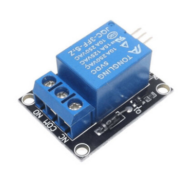
1 Channel Relay Module 5V Optocoupler LED for Arduino Pic ARM AVR
As I got into the detectors, I realized that not only the range was a problem, but putting them in some kind of structure so they could “see” a train going by would also be difficult.
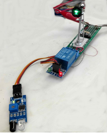
Here is my little test board with a detector not detecting anything.
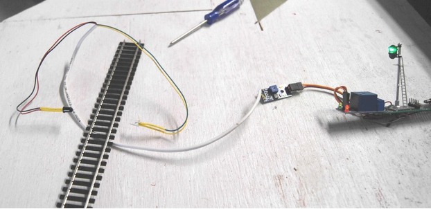
I wondered if I could remove the IR LED and Detector LED, and if they needed to have a specific wire lead length. I decided to try to un-solder the IR-LED and Detector LED and extend them on longer wires, this allows for them to be hidden in most anything on the railroad, like in cars waiting at a grade crossing, or in a little signal box next to a switch.
Some care needs to be taken as the little IR Led and Detector are unsoldered, wires extended, and shrink tubing applied. Be careful not the lose the polarity. I added about a foot of wire, and 6” to each LED, like below.
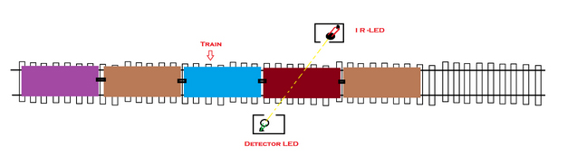
Since they face each other now, their mode switched and they send a detect signal until the space between them is blocked, out of the box and mounted side-by-side, they look for reflected IR so they are normally not detecting.
So, how to detect the trains without blinking as the detector “sees” the spaces between the cars? Decided to shoot the beam on an angle like below:
My signals, most from China, are LED common cathode, so the schematic shown above is how to wire them with that configuration. If common anode, reverse the + common to the relay and connect the negative to the LED’s. What I found is that when the IR and Detector are facing each other, the range is reallly increased. I easily detected a card blocking the beam from more than 6”
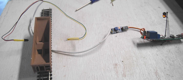
When my test railcar even gets close, the detector hits it and the detector will report “track occupied” to the relay, which turns the signal red. I’m planning on also having a parallel LED on my control board to also see where my trains are, and what tracks are occupied.
Next project is rebuilding a roundhouse turn-table! Everyone be safe, and happy modeling!
John from Baltimore.”
Lastly for today, Cassio has sent this video in.
He’s never a man of many words – or any come to think of it – but I enjoy his videos:
A big thanks to John for sharing his infrared detectors for model trains ‘how to’. Thanks to Cassio also.
(John’s post reminded me of Mark’s: Model train block dectectors.)
That’s all for today folks.
Please do keep ’em coming.
And if you’d like to make that start on your layout, the Beginner’s Guide is here.
Best
Al
PS Don’t forget the latest ebay cheat sheet is here. Still updated daily.
PPS More HO scale train layouts here if that’s your thing.


John,
Thanks for sharing your research and expertise. I need an application like what you described. My track 1 has a passing siding under the station. I typically have two passenger trains on track 1 in opposite directions. When I am preparing to shut one down it take a keen eye to bring the engine up far enough without fouling the turnout. I have long thought of installing a sensor but it’s been down on the the list. I just had a problem because I didn’t pull up far enough; and then I see your post. Nii I w I have a path forward. Thanks again.
Bob in Colts Neck Crossing, NJ
John from Baltimore you are brilliant, I’ve been trying to do the same. Didn’t think of that.
Great work
David from Violet Town Australia
John, nice idea but a lot of work. I have something similar made by Heatcote Electronics. Clive Heatcote makes various electronic boards for model trains and their benefit is that the sensors are smaller,can be fitted between the track sleepers, wiring is simple including LED to a control panel,allow for the gap between coaches and best of all cut the power off in front of the signal so another train cannot pass. Great for setting up block systems. Have used them for 20 years trouble free on bothDC and DCC.
Thanks a ton, John. Very interesting and very useful. Something that I have been wanting to do for a long time but not got round to.
Thanks Cassio- love to see trains running!
John
Great job. Azatraz is a firm with detector systems and signals that I think are reasonable and all should check out.
All be safe
George from NY
John Nice idea. May try this myself. Thanks
I use a set up similar to this to operate my snap switches, I mounted the IR light on the car and the sensor on a dowel rod. works great and cheap too
Have you tried adding fiber optic cable to the LEDs. That might let you hide them in tight places. I add the fiber cable to LEDs with heat shrink for remote lighting.
Went on line as soon as I read this and was able to source a couple from West Australia – delivery in less than a week, bonus!
Fred Driver,
Victor Harbor South Aussie.
John, Thanks for the detailed description. I did something similar, using Light Dependent Resistors (LDR’s) through a voltage divider (by using two LDR’s, one acts as a light compensator so that the divider remains constant no matter what light level). The ‘sample’ voltage then passes into an Arduino ProMini. With simple code, outputs can be obtained to apply 5v or 0v as required. I use this for RED or GREEN LED’s. I have pondered about using IR’s, but not done so as yet. I am happy to send details if you require.
John, Great detailed explanation of your circuit design process. I’m not into signaling yet but appreciate the knowledge for future reference.
Cassio, As a Union Pacific fan, I loved your video. Please send more when you can. I have a UP mainline just a half mile west of my house where I can watch them roll by day and night.
John, thanks for the detailed information. Could you make a detailed list of everything that needs to be purchased and a step by step instructions on how to set this up and how to wire it. I’m sure that a lot of modelers would also love it.