Bob’s been back in touch with some more details on terminal strip model train wiring.
He’s been kind enough to write a response after all the comments on his last post, which is here.
“Alastair,
In response to comments on my last post here is some info on my terminal strip model train wiring.
First off I am not an electrician. I spent 14 years in the Infantry and 38 years as a programmer and systems administration.
The wiring looks daunting, but it is quite simple if you take your time and do not rush.
I have found that ‘Spaghetti Bowl” and “rats’ nest” wiring come from rushing.
Right now, my track wiring is looks messy because I am testing to make sure everything is working. The key is to make sure I clean it up once I verify the everything works, and I will. I am taking my time this go around.
The first picture shows my track plan. There is a double main that has four signal blocks on each main. The first block of each main is at the top between the tick marks. The outer main blocks are numbered counterclockwise 1,2,3,4 and the inner main blocks go clockwise 1,2,3,4.
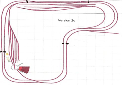
I am using Arduino to read the IR sensors and to control the signals.
There is an IR sensor at the beginning and the end of each block and a three head signal mast at each end of each block.
The second picture shows how I have mounted an Arduino and wired it to three terminal blocks. Each is wired to communicate with the next block(Block A) and the previous block(Block B) and an intersecting tack(Block C).
There are three places where there are tracks that allow access into the block between the sensors.
Note in the upper right quadrant there are tracks entering the mains.
At the bottom of the layout there is an access track for the turntable.
In the upper left quadrant, the track from the yard joins the inner main. Each is wired for three sensors and three signal lights because of these four mid-block access points. These four tracks are the Block C respectively. That is enough about the blocks. On to the wiring.
This picture shows the wiring of one of the eight main blocks. The Block C sections are controlled slightly differently but have the same wiring setup.

Terminal strip model train wiring 1:
Pin Connection
1 Positive connection 5v
2 Positive connection for Sensor1 (Black wire)
3 Positive connection for Sensor2 (Black wire)
4 Positive connection for Sensor3 (Black wire)( Note: This gets use when there is a spur in the middle of the Block: e.g., yard entering the main , track from turn table connecting to main.
5 Positive connection for Signal 1 (Black wire)
6 Positive connection for Signal 2 (Black wire)
7 Positive connection for Signal 3 (Black wire common on the signal) (Note: This is used when there is Block C)
8 GND connection from Arduino
9 Common GND for Block A
10 Common GND for Block B
11 Common GND for Block C (Note: This is used when there is a Block C)
12 Not Used
Terminal strip model train wiring 2:
Pin Connection
GND connection
Sensor1 data connects to analog pin A0
Sensor2 data connects to analog pin A1
Sensor3 data connects to analog pin A2
BlockARec connects to analog pin A2
BlockBRec connect to analog pin A3
BlockCRec connects to analog pin A4
Red – Signal 3 connects to digital 4
Yellow – Signal 3 Connects digital pin3
Green – Signal 3 Connects digital pin 2
Block A send connects to digital pin 8
Block B send connects to digital pin 9
Terminal strip model train wiring 3:
Pin Connection
Red Connection for Signal 1 – Connected to digital pin 4
Yellow connection for Signal 1 – Connected to digital pin 3
Green connection for Signal 1 – Connected to digital pin 2
Red Connection for Signal 2 – Connected to digital pin 7
Yellow Connection for Signal 2 – Connected to digital pin 6
Green Connection for Signal 2 – Connected to digital pin 5
Red Connection for Signal 3 – Connected to digital pin 13
Yellow Connection for Signal 3 – Connected to digital pin 12
Green Connection for Signal 3 – Connected to digital pin 11
Block C send Connected to digital pin 10
Block B send Connected to digital pin 9
Block A send Connected to digital pin 8
Maybe too much info but I hope it is useful and convinces some to take the plung.
Bob in Virginia”
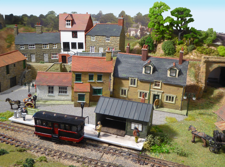
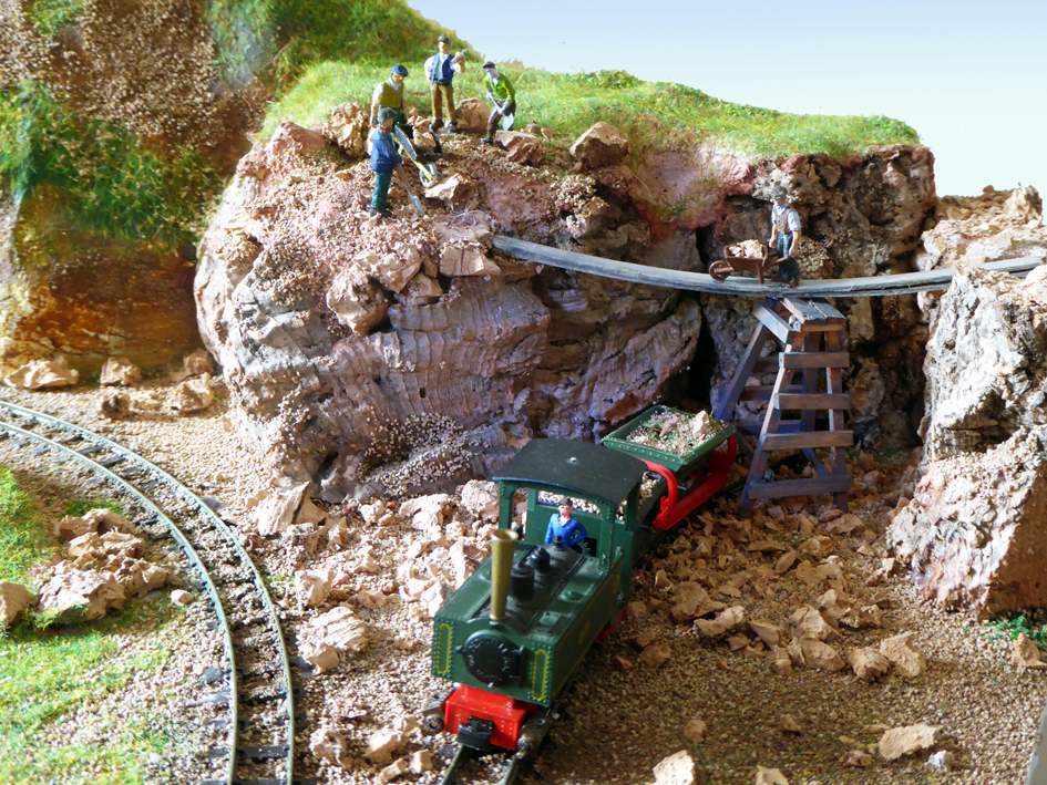
Now on to Keith – and I absolutely love what he’s done, particularly the scene of the men working:
“Alastair:
I have not seen any British narrow gauge railways in your blogs so I thought your readers might find this of interest.
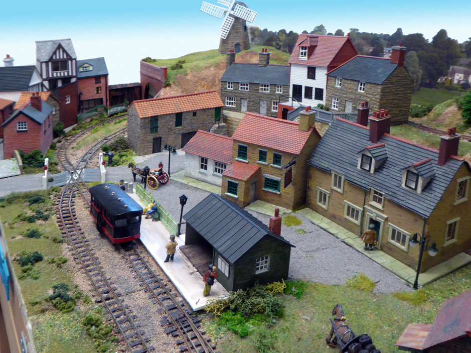
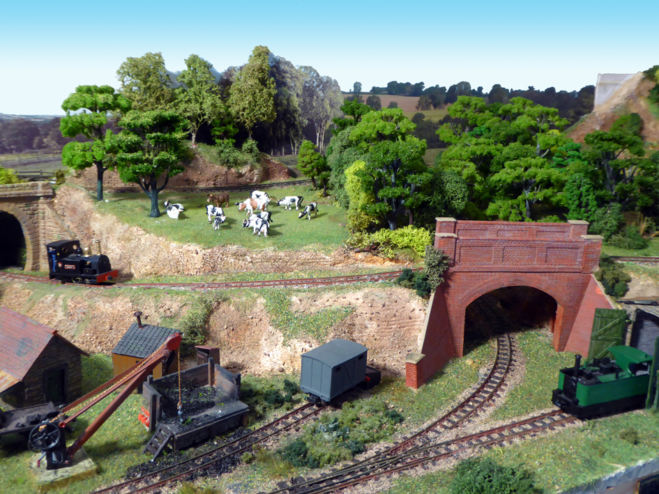
The Sibford Quarry Railway is a 4mm scale narrow gauge layout set in the British Cotswolds.
There is no railway in the Sibfords where I live but you can find Sibford Gower and Sibford Ferris on the map either side of the river Sib (at its widest about 3feet).
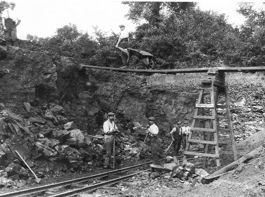
The quarry however is real although worked out before the Second World War. See the black and white photo.
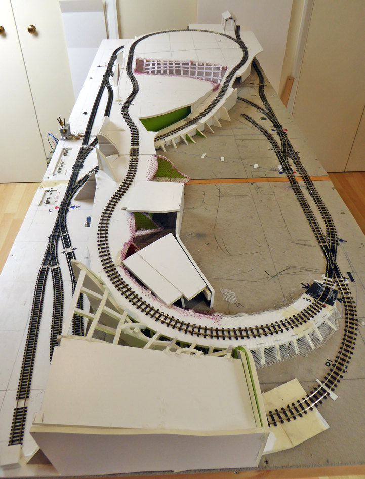
This version is the latest in several built over the last twenty years, is portable and fits easily in my SUV. It measures 2ft 6in by 6ft and comes in two sections that clip together.
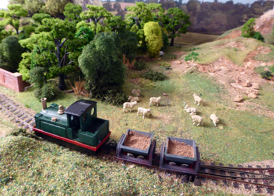
Since last year I have been converting all my locos to radio control; quite a challenge considering the size of 009 locos. To date I have completed four. This means I have no problems with track cleaning or electrics. The points (turnouts) are controlled through a ‘wire in tube’ method.
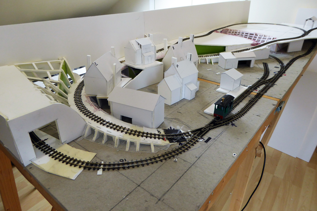
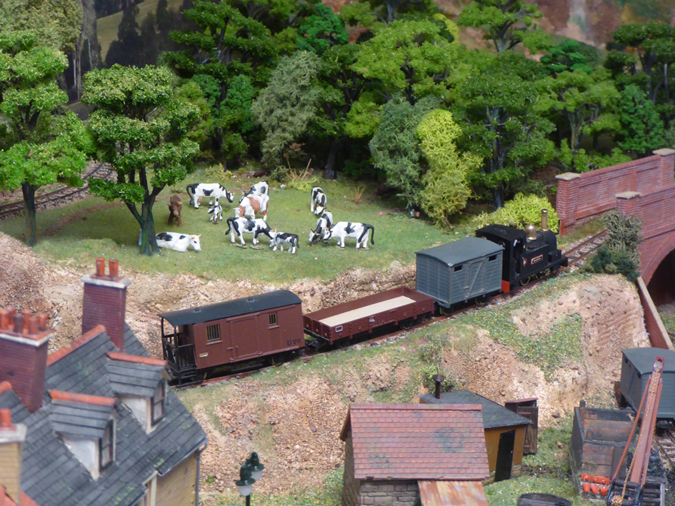
The majority of the structures are scratch built and are based on buildings in or around my village.
The scenic structure uses 5mm foam board which is strong, very light and easy to work with a craft knife. This, where appropriate, is covered with plaster bandage dipped in a dyed water solution to take away the whiteness.
I enjoy the scenic side of the hobby most but have running sessions when the grandchildren come (not since March of course)!
Keith”

A huge thanks to Bob for sharing his terminal strip model train wiring, and to Keith.
Bob frazzled my brain, and Keith put a big smile on my face with that workman scene from the photo. Loved it.
That’s all for today folks.
Please do keep ’em coming.
Don’t forget the Beginner’s Guide is here if you want to join in with the fun.
Best
Al
PS Latest ebay cheat sheet is here


WOW fantastic job!!!
Bob Thanks for taking the time to go into such detail about the wiring of the signals and there inter-relationship. I’m sure it will inspire people to give it a go.
Keith What a fine narrow gauge railway. Your attention to detail and scale is outstanding. Many could take note of the scale and size of your rock work and boulders. Also the tree coverage is well planned and the number of trees grouped together helps give the impression of realism of the woods rather than the odd tree scattered here and there. A really nice layout Well done.
Hi Keith,
Nice one, I’m in Lower Taddy and my N gauge layout is loosely based on on GWR 1950’s My main feature being a working canal and quarry staithe running through it.We are of course not far from the Wroxton/ Horley Ironstone railway which would be a good subject for a quarry scene. Perhaps meet up and share a jar after the lockdown.
Best Wishes
Tim
Well Bob I’m sure it all works but it’s not that easy to follow.
For starters you don’t mention that the connections to terminal 1 aren’t shown in the picture!
Then you’re using black wires for positive voltage! Most confusing.
Glad to see your using the Arduino. I’ve used those for block detection, speed and direction displays as well as engine and point control – both DC and DCC.
With later microprocessors you can make all communication wireless too.
Keep up the good work.
Regards Luen.
Wow, that’s fantastic! *
A great job and a pleasure to see!
* “Wow, that’s fantastic,” an acceptable definition of “WTF,” subject to Al’s editorial scrutiny and approval.
Keith – I am not often inspired to take the time to comment on Al’s forum, but your wonderful, perfect little narrow gauge layout has such a happy, pleasant, utopian feel to it, that I just had to applaud your work.
I enjoyed scrolling back and forth to compare the real photo and the model scene. Although they are a bit different, you nailed it. WOW, Cheers! NJ Mark
Excellent layout, love the detail.
Wonderful job Keith. Gives me some ideas. It all takes patience and time but the results are rewarding.
Now as to my post on my signal control, thanks for the comments. I am documenting as I go. I haven’t connected the sensors and signal masts yet. I built the control board first. On the board each terminal block has 12 connections numbered from left to right. I am using phone wire to connect the signal masts because it has four wires: green, red, yellow, and black. The signal mast have four wires: green, red, yellow, and black. The black wire is the common anode and is connected to the positive so that the green, red, and yellow wires connect to their respective color LED. All of the wiring shown is from the Arduino to the three terminal blocks. The open connections on the terminal blocks are where the respective wires from the IR sensors and signal mast connect. My system is a slight modification of the system I found on YouTube for ” Arduino Multi Block Signaling.” I added a section for three signals and three sensors.
Keith, the buildings are great. Your scratch building skills are extraordinary. Nice layout.
Jack in Pa
Terrific landscaping and details. I am familiar with the spaghetti wiring. I am slowly rewiring my layout and still have some of that left. I have to be careful, though, I missed a connection and had to spend a lot of time finding it. But thanks for your contribution to wiring issues that plague many of us.
Two great posts- Thanks Bob and Keith! I hope you both keep us updated. Keith, I’d like to hear more about your radio control conversions. Love the quarry!
Hi I have a question that I hope your readers can help me with. I am sorry I have no pictures. I found a plan for a steam plant. The plan is for O gauge and in inches. I would like to build the steam plant in HO. Should I keep measurements the same or should I half the measurements. For example length is 10 inches for O gauge should I go 5 inches. Height is 6 inches should I go 3 inches. Halving the measurements make the plant look to small. Any ideas would be helpful. I have enjoyed all the post.
Keith…the Quarry detail is outstanding, but more important to me is the overall “feeling” that I get looking at your layout…I really want to walk about there. It is so ‘comfortable’ looking.
Thank you for sharing,
Kirk
Would like to see more detail of your connections to signals etc and, not having used an Arduino before, would love to see your program listing.
Good ideas!
Hi Keith, that is an excellent job that you have done on your narrow gauge railway. Fine detailing on your scenery and buildings. That layout is something to be proud of.
Electronics scare me…
They have since I was in Junior High School — In the 1970’s.
That gauge layout is amazing…
Very realistic scenery and the picture of the workmen… WOW!
Then there is the story of the River Sib… That gave me a good chuckle.
Thats a great layout you have built there Keith , nice to see N gauge , just wish my eyesight was good enough to build in the smaller gauge , well done …
ED, 6 inches in O scale would be 24ft. So in HO it would be 3.31 inches.
As I mentioned, I am documenting as I go along and I will post more on the signaling once I have it complete. I will post a picture of one of the Arduino control blocks with all of the connections and an explanation. I also plan on doing a video
Hey, just learned a new word/term. “Arduino”, had to look it up. Cool device for just about everything. How did I miss this for almost 80 years? See, we do continue learning. As I build my next layout, it will be used. Paul
Hey Keith. Love to share ideas about Ardruino. I’m thinking of using them for block PWM control on a Christmas set-up. Job well done.
I’m not sure the Health and Safety Inspector will be very happy to see 80 year old quarry working practices still in use today. LOL Andrew
Great Layout!!
great keep up the great work. sheldon
Bob, what a thorough explanation of your block wiring. I can understand the basic gist of what you’re doing but I doubt I could have ever figured out the wiring plan on my own. So, If I understandit right, there are 8 Arduinos total — one for each mainline block. I am curious about the logic behind numbering the blocks of one mainline clockwise and the other counterclockwise. It seems to me that’s more confusing than if adjacent mainline blocks had the same numbers or just number one mainline 1-4 and the other 5-8.
Keith, Thank you for sharing your wonderful Sibford Quarry Ry. photos. The finished layout is very interesting and quite impressive. I love all your scratch built buildings and your accurate representation of the actual quarry. Being able to see that original photo of the quarry makes the layout all the more interesting. What brand of narrow gauge track did you use for the layout? I can see that you enjoy the scenicking part of the hobby because your scenery is so well done.
Finally, thanks to Al for making this all possible.
Ed, Since O scale is 1/48 and HO scale is 1/87, if you multiply each dimension by 48 and divide it by 87 you’ll get the right HO proportions. You can also just multiply each O scale dimension by 0.551724 and it will give you the corresponding HO dimension in inches. Unfortunately, when HO (Half O Scale) was created, they decided to use 3.5 mm per foot instead of 1/8 inch per foot. So HO in not truly half of O scale which is why just halving the O scale dimensions you have would make the boiler too small.
Will in NM: The track is Peco 009 ‘crazy track’
Absolutely lovely layout, Keith!
WOW , Best of luck and may you have many enjoyable hours running your pike . I love your scenery and landscaping . Although I am a hi-rail O person , I do take many ideas from other scales .
Very nicely done, Keith. Your landscaping scenes are quite realistic and the town with those great looking buildings is as well. You have some great modeling skills. Thanks for sharing.
Jim AZ
Just about THE cutest l’il layout I’ve seen! EXCELLENT scenery job! LOVE it!!
Chuck
Roanoke, VA
Forgot to mention that some of the buildings remind me of those seen on the PBS TV show “Doc Martin,” ,which my wife and I LOVE!
Chuck
Roanoke, VA (again)
Keith, like Tony I would be interested to learn how you have arranged for radio control of your 009 locos. Is everything packed into the locos or do they need match trucks/wagons/coaches to hold some of the equipment?
Just have to comment on your layout Keith. It’s great to see something different come up on the blog. And, I just find it absolutely perfect. It just all works together so well, the railway, the buildings and scenery. It goes into my premier league classification. Well done.
Best to all.
Brian, Wokingham, UK
Bob in Virginia. I too used Arduino & IR to detect trains and operate signals. I have 2 x dc loops, each with 4 blocks. I incorporated an interface board to the Arduino, so as to use the Arduino outputs for other functions. I would be very interested to see your sketch (code). I am happy to send mine. A comparison could be interesting would it not? I also used IR / Arduino for a ‘train at station’ recognition, and hence a platform announcement. I am happy to share ccts etc with anyone.
Steve White (Sydney)
Fantastic detail, Keith. I too, scrolled between the original photo and your reconstruction and you really captured the mood and essence of days gone by.
Well done.