Lawrence has been in touch because of his model train incline.
Like many of us, he found out the hard way what is acceptable when it comes to running trains up an incline.
“Hi Al
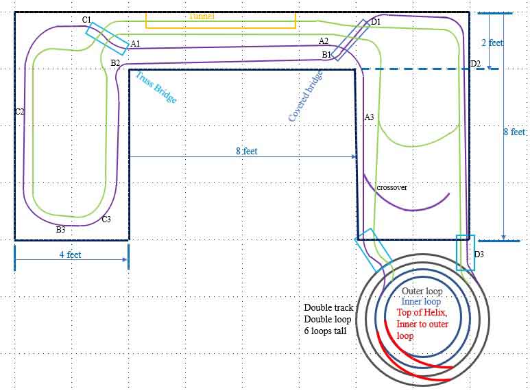
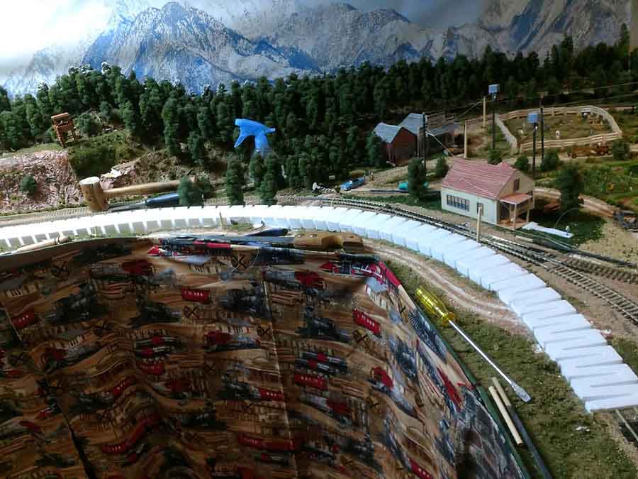
The following pictures are all referenced to the first picture that displays the layout that I have.
When I initially built the layout, I did not know what I was doing when it came to inclines. Since then I found the formula for determining the percent of grade.
I was having trouble with trains going uphill and using the formula I found out that I made grades from 3.5% to 5.5%. The optimum is 2%. My model train incline was too steep.
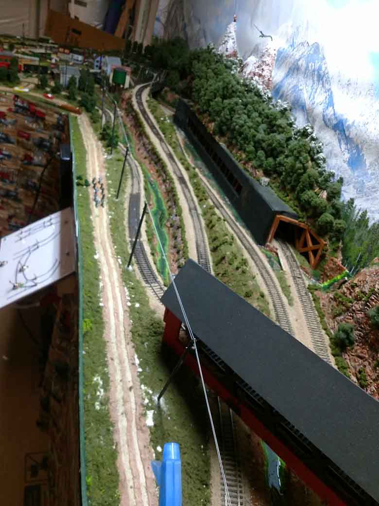
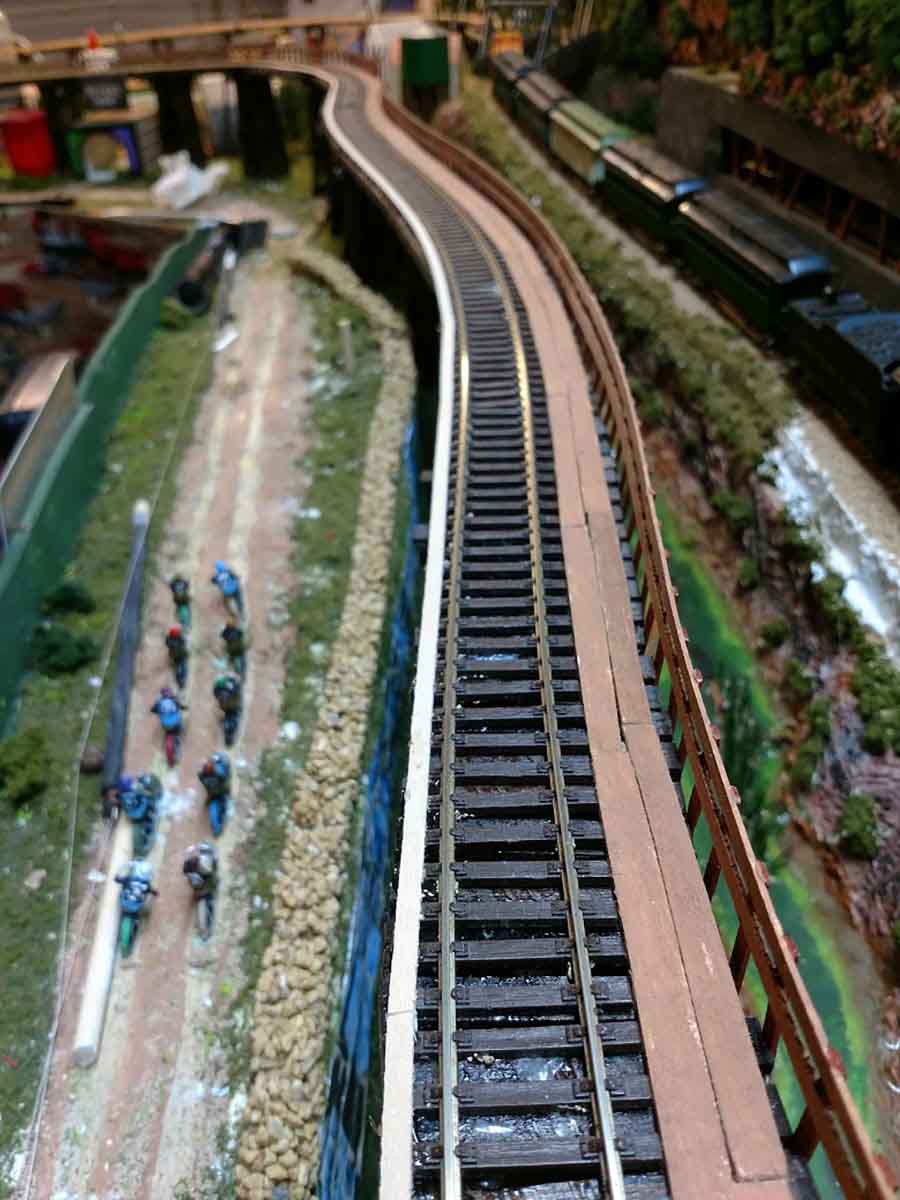
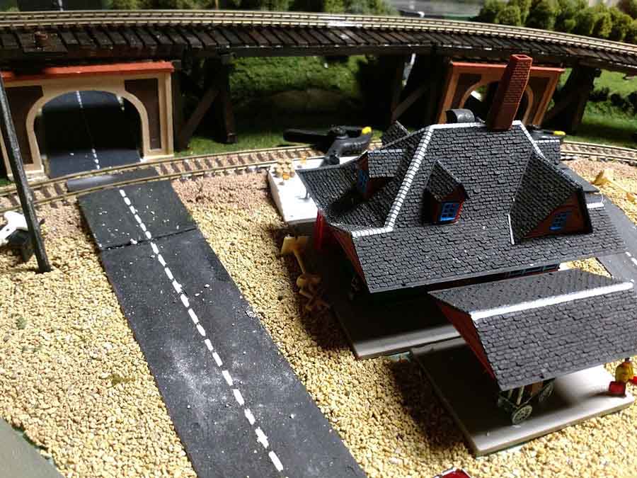
Example A1 to A2 was 5.5%, to make it 2% I had to change the rise from A1 to A3 (on the diagram). The A1-A2 track goes from the top to under the covered bridge. The B1-B2 track, at 3.9% goes from the covered bridge.
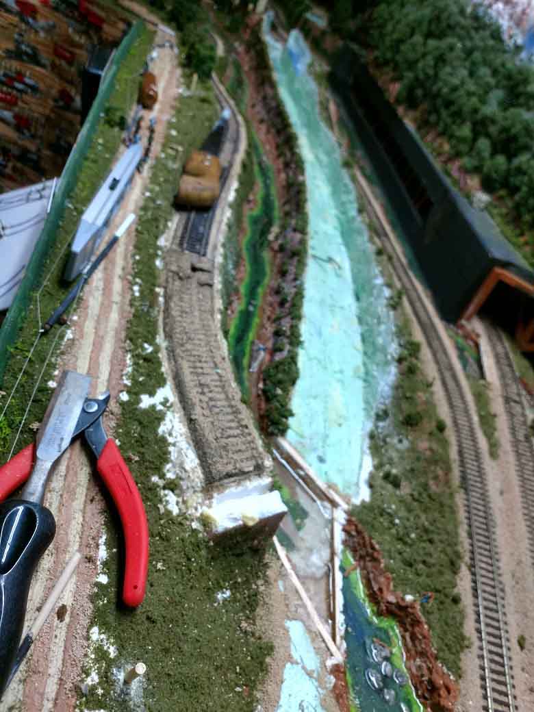
Another angle of the two mentioned tracks before reconstruction. I wanted to pull the track without having to redo all the scenery. Lifting the covered bridge off the layout and starting to remove the track to the base foam layer at the lower end (A2 area).
Cutting out the track at the upper end, cutting down to the base foam but keeping the scenery intact as much as possible on either side. Another shot of the A1 section of the track area cut out. the smaller bridge also had to be temp taken out.
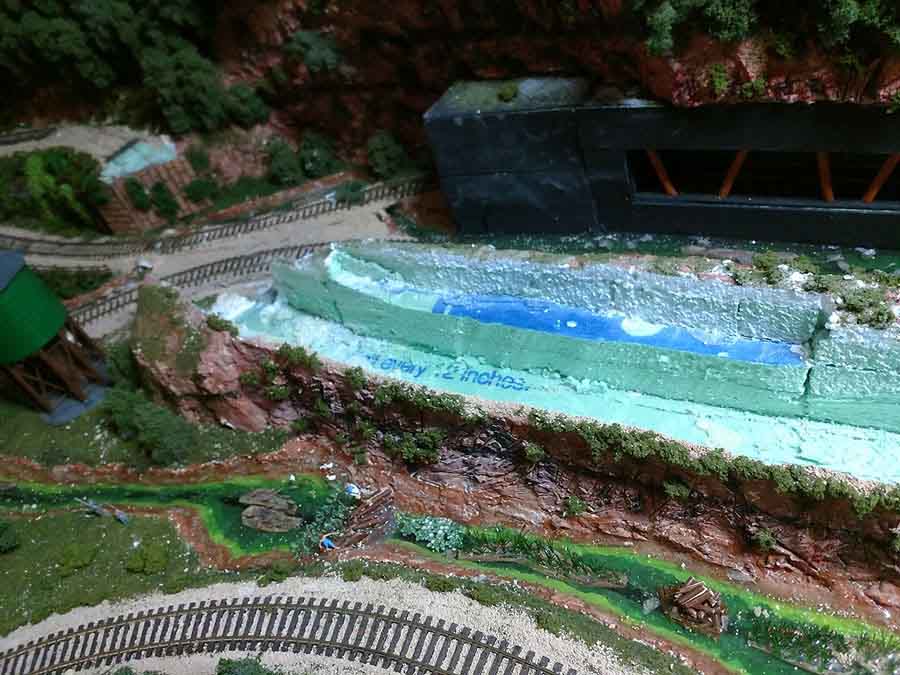
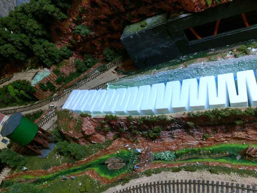
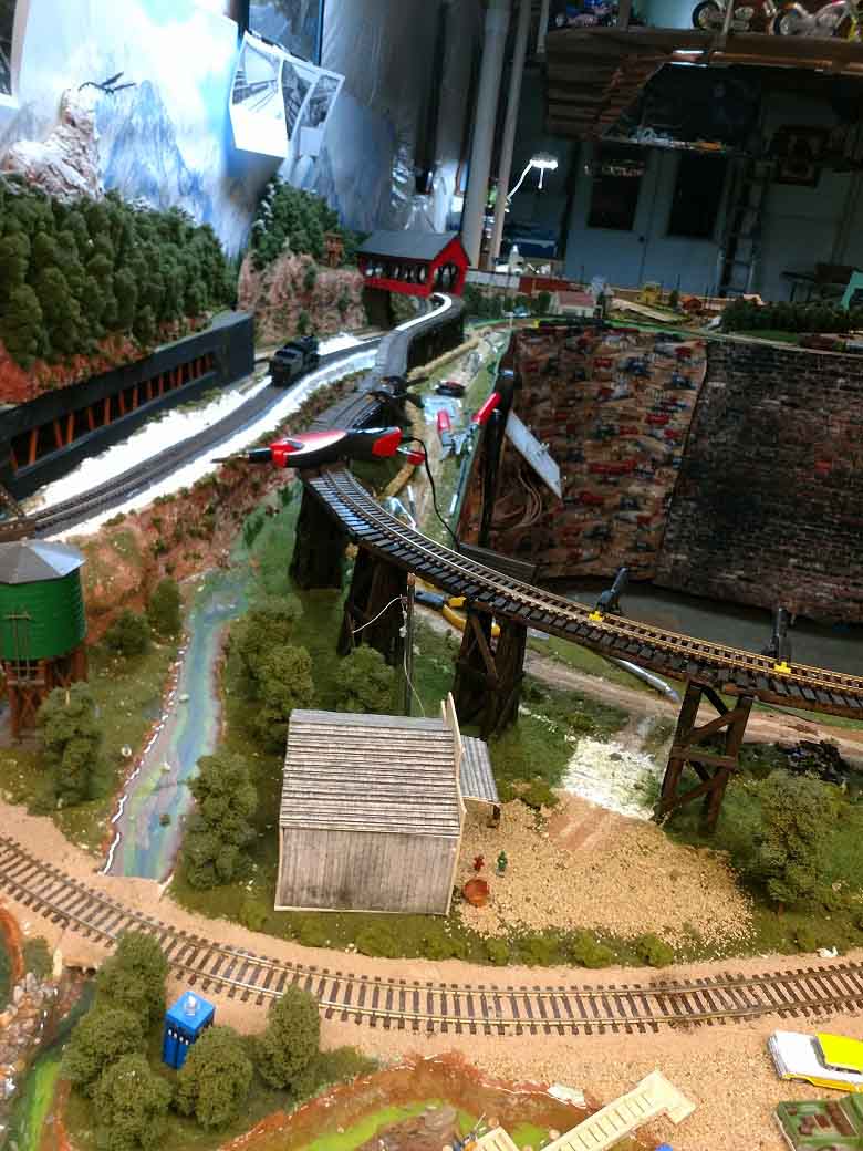
The upper end of the A1 section with the store bought 2% grade foam in place. The middle section of the 2% foam in place. this is where I found out at the level of the track under the covered bridge would be 2 inches higher than before. This is a problem as before the change there was only one quarter of an inch clearance for the train to travel under the bridge. Laying the 2% foam around to the now A3 location after puling all the track to this point. The D section of track was handled in the same way. BUT – –
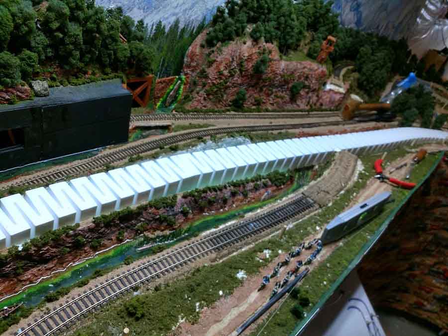
Forcing the B1 section to now be raised from 3 inches to 5 inches the B3 section goes around to the new B3 area. BUT – – The C1-C2 section over lapped the B3 section. PLUS, at the B3-C3 area two roads cross the bridge.
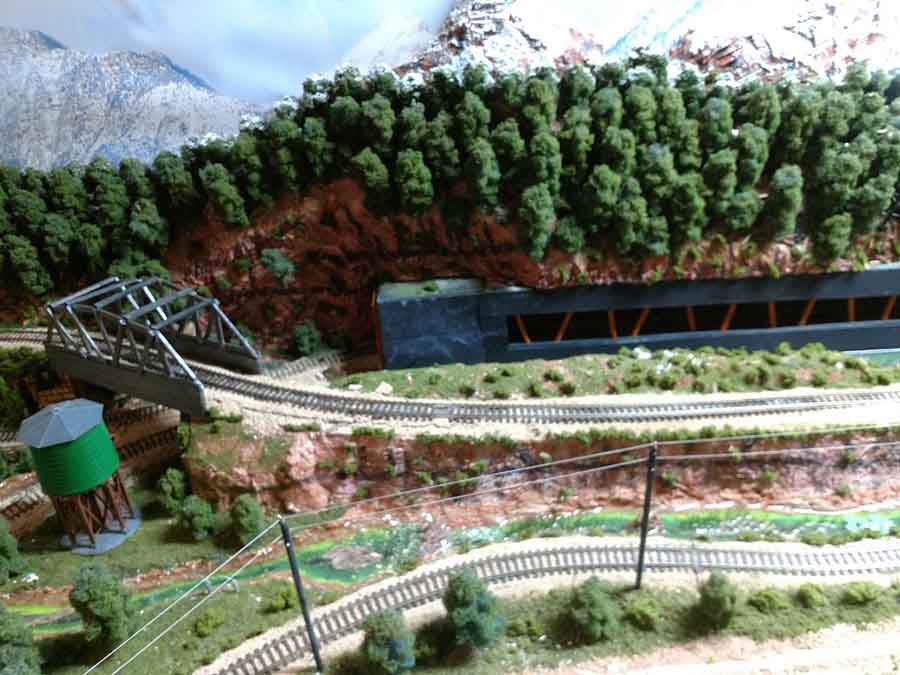
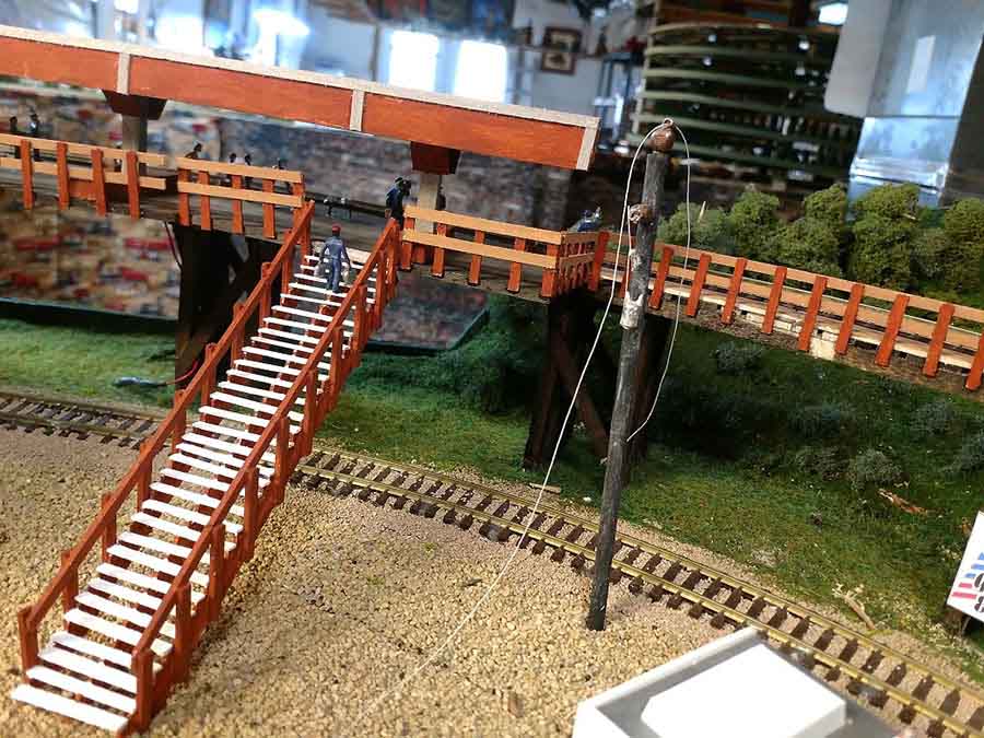
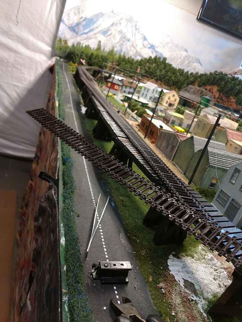
To solve the problem a Trestle bridge had to be built from B1 all the way around to C1. Here the bridge goes over the road (under construction) to the Antique shop.
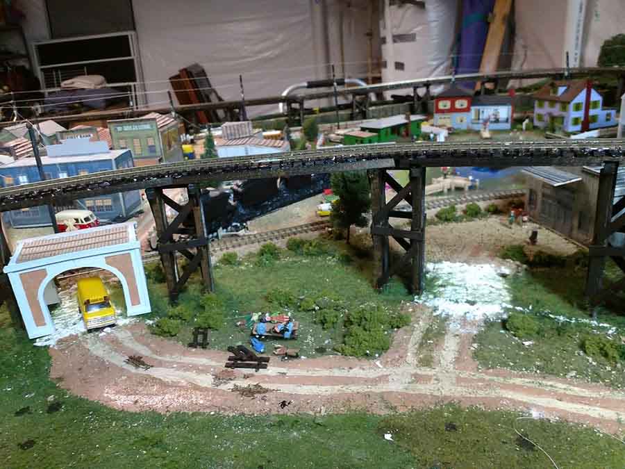
The B section of the Trestle, in the foreground, and the C section to the rear. N gauge train tunnels built for the HO gauge layout for auto traffic.The train is on the mostly finished A section of track.
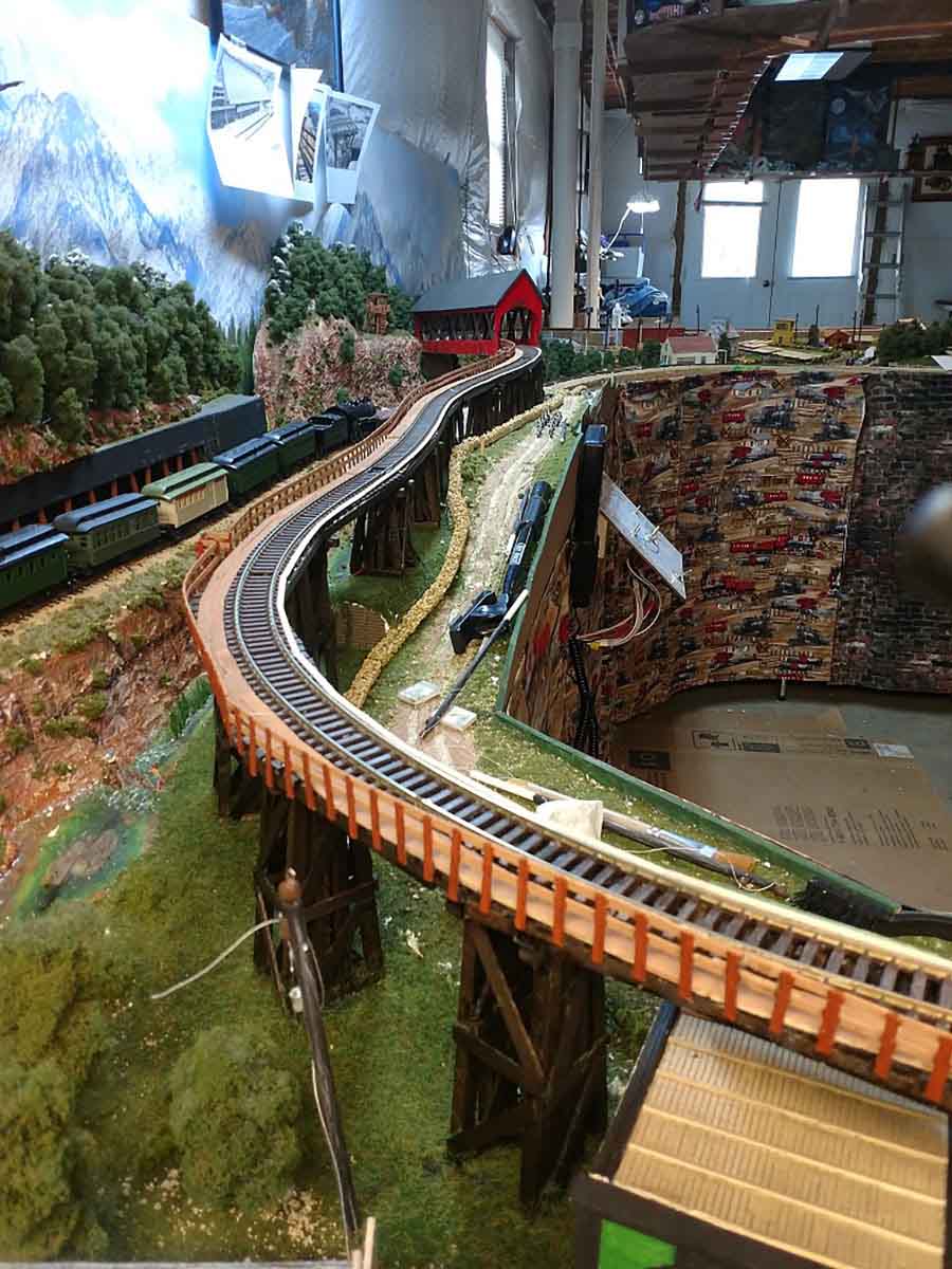
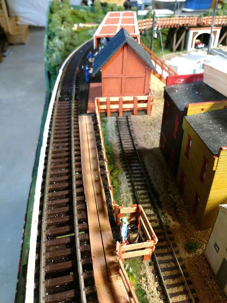
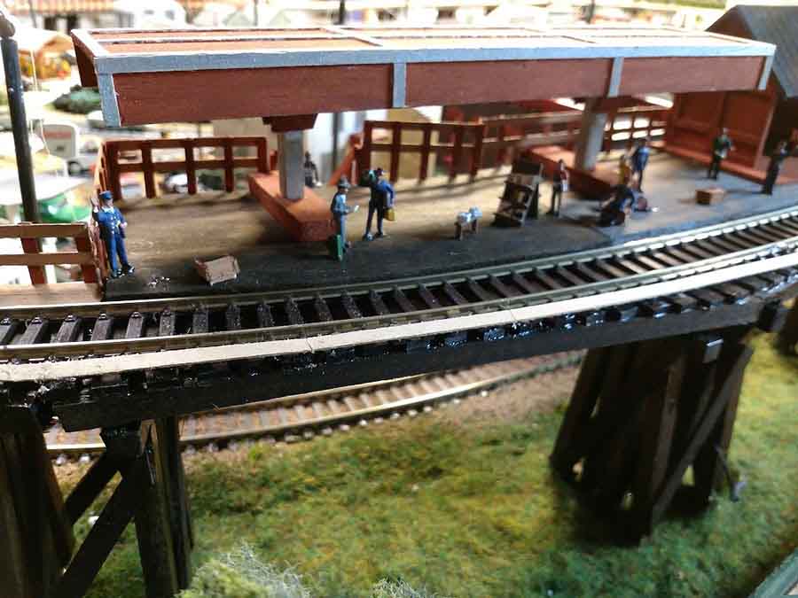
The trestle has a walkway for the engineers and a banister for safety. Another pic of the A1 section of trestle track finished. About where the A2 area was a new raised train waiting station for passengers.Another angle of the passenger station. Also, the water barrel in place for the steam engine usage. The passenger station and news stand.
The two roads going under the trestle bridge with the N gauge tunnels. The trestle had to be raised not the 1-inch minimum need for the 2% grade in both directions but another inch to allow for the auto tunnels. Laying the track around the C section. The actual last to be worked on at this time.
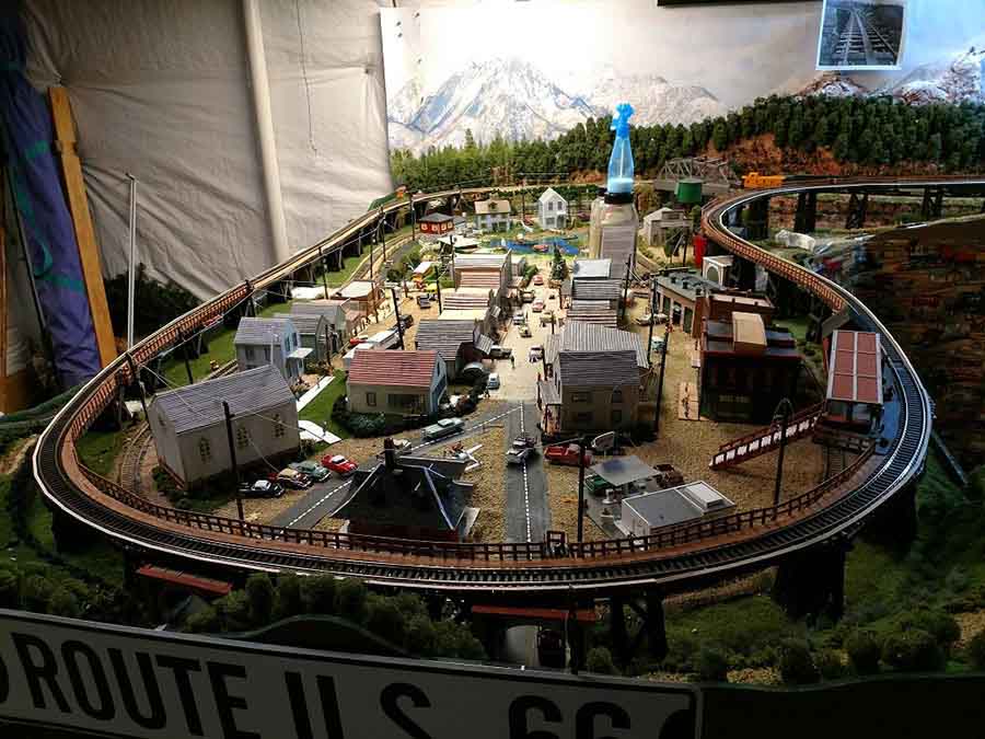
And last off is a pic of the overall area for the trestle bridge – it shows the my model train incline – from the upper right, around the town, to the middle back. The banister still not finished in the C section. That is physically 20 feet of layout trestle track.
Lawrence”
Model train incline:
A huge thanks to Lawrence for putting this together. Just goes to show a model train incline is no different to any other part of scenery – one small change to your track means lots of other changes need to happen too…
That’s all for today folks – but please don’t forget the Beginner’s Guide if you want to get going on your own layout and side step the mistakes we all make.
Keep ’em coming.
Best
Al
PS Latest ebay cheat sheet here.
PPS And if you fancy reading even more on inclines, this post will help.
PPPS Here’s another great incline ‘how to’ as well.


I had problems with inclines as well, mine was 4%. To solve the problem I added 3” to two sides of my platform and took the inclines out. Everything runs much better.
That length of trestle is a real tour de force, you have the patience of a saint. I would just have put in a short spur track at the bottom of the five percent grade with a water tank and a little bothy, and kept a helper engine there to assist trains to the top then run back light to the spur. More fun, less work. But then I’m lazy!
Rod
Alot of action going on very busy town love it. Now modernizing the train system to diesels.I’m not a choo choo guy and I’m 70. i’m a 80’s to date locomotive enthusiast,but to each his own.
Robert B
Ah yes! Been there. I tried to install a helix on a 46 inch circle climbing up 12 inches, in 1/64 scale. This meant the helix was at 3.;5% grade. 1/64 scale trains will not make this grade!! After going up 2 circles, ripped it all out and installed a incline up to 5 inches and then went flat on a reversing loop back to the switch. This allowed the on deck train to travel underneath the incline. I came about and ducked under at 5 inches. This picked up 6 inches of benchwork surface for other elements. I created an aqua duct with open inches so I could see the lower train. Be sure you can pull the inside of the incline slope out to service a train off the rails. Same goes for mountains, be sure you can get inside. Quick note, very 50 inches of incline allows you to raise the slope 1 inch. I shot mine with a laser. Stay off the backdrop a good 1.75 inches to to the roadbed to allow for flat buildings and such.
Real nice layout & a great job on that unique trestle. Kudos to you for solving the grade problem. The mountain backdrop looks fantastic. Jim from CB.
In the track plan there is a helix. Another photo shows the helix in the background. It looks quite large. There is no info on what the helix is connected to. In another photo there is what looks like a railroad layout hanging from the ceiling. If true it would be great if Lawrence posted pics and info on this part of his layout.
Lawrence
Thanks for this article I am actually building my first layout and I will be having an incline to my staging yard. This was very helpful thanks again Alistair Lee, and once I start making a little progress I’ll send some pics.
I learned about grade when I was 12 (now 63). I used flex track and started the upgrade at the rail joiner, well the grade was too steep and the joiner bent, so the first time I ran my Mikado (tyco kit) the front step shorted out the rails, lesson learned on grade, starting grade at a joiner and time to change the supply fuse.
Have you ever come across Powerbase from DCCconcepts? Makes most inclines easy to achieve by majority of locomotives. Really helps when space is an issue.
Regards
Matt
Re Matt’s comment on Powerbase, it’s something I intend to use on my proposed inclines. It looks very useful but very hard to “retrofit” if your track is already in situ!
It’s really an adapation of Tri-ang’s old “Magnadhesion”, where the loco chassis had a magnet built into it which caused extra downforce onto the steel rails. Track these days tends to use non-magnetic rails, so the Powerbase system consists of a magnetic sub-base laid beneath the track and tiny magnets which are fitted to the base of the loco chassis. I have purchased some of the baseplate packs but haven’t seen any of the magnets yet – I assume that they are neodymium ones.
Hi Lawrence,,, Nice Layout…really like the photos… Spotted the “Tardus” in Photo No.9. Looked at the next couple of photos…. No. 13.,, Looking down from the Elevated Station Platform onto the Staircase… Folks would be really winded by the time they reached the top carrying anything. Could you advise the Supertendent he could direct a crew to extend the top of the Staircase out 10 ft straight over the tracks, then split the staircase in two sections with a landing halfway down. That would help people out..Photo No. 14, next,, On the Elevated Line, there is a bump out from the platform with someone standing there with a “Fire Barrel”. I couldn’t help but notice the columns supporting that bump out… actually blocks the side of the railroad track below… Unless that track behind the buildings is abandoned.. no freight car or engine would make it past the elevated platform support columns.. Maybe a letter to the Superintendent would suggest he make the bump out Narrower just for a barrel width, so the track below could be utilized better if it’s not abandoned. Like the Covered Bridge by the way….
What I did once was to incline the whole platform the opposite direction to make the incline look steeper than it really was