George has been in touch with his excellent ‘how to’ on a model railroad crossing:
“Big Al:
This diatribe is how I am providing crossing signals at roads crossing tracks.
There are IR sensors to sense incoming trains and the gates go up & down with flashing red lights. All gates are scratch built.
Commercial products ( very hard to get ) that do the same thing cost at least $180 a crossing with all the electronics and at 9 crossings this amounts to $1600 that I aint got.
First I cant thank John Frye enough for his submission to the infamous Al Lee site regarding IR signals because I would have never been able to do this without his brilliance.
The materials are available on Evil bay and Amazon and I figure it costs about $20 per crossing plus wiring and a lot of labor and swearing.
I am now looking into 3D printing the actual crossings because they’ll look & work better than the shop built prototype.
IR detector: Arduino PIC AVR IR Infrared Obstacle Avoidance Sensor Module Object Detector- about $2.00 ea.
Relay: 1 Channel Relay Module 5V Optocoupler LED for Arduino Pic ARM A. About $3.00 ea
Servo testor 3CH -about $3.00 ea. MG90S 9g Servo Motor Micro Metal Gear- About $4.00 ea. (2 rqd). Female ended 3 wire cables for servos.
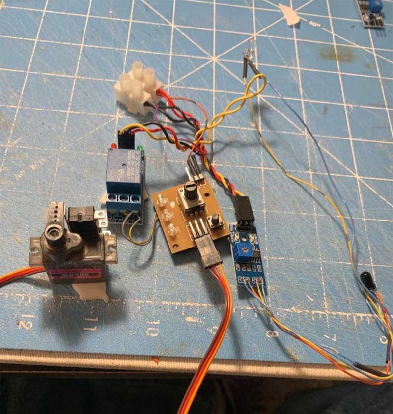
This pic is of the prototype that actually works when I pass my hand between the IR bulbs.
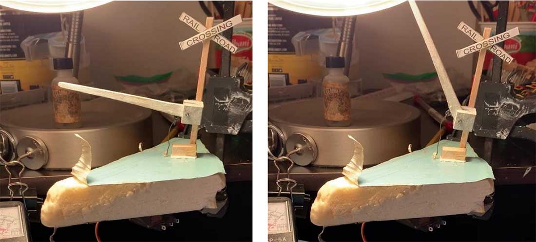
The servo motor is under the foam, has a piano wire connect to it and the arm of the signal above.
The signal was made from wooden stirrers, hard maple for the base & turret & 18” ply for the arm. The lights will come later. Again I’m not content with the look and planning to 3D print this.
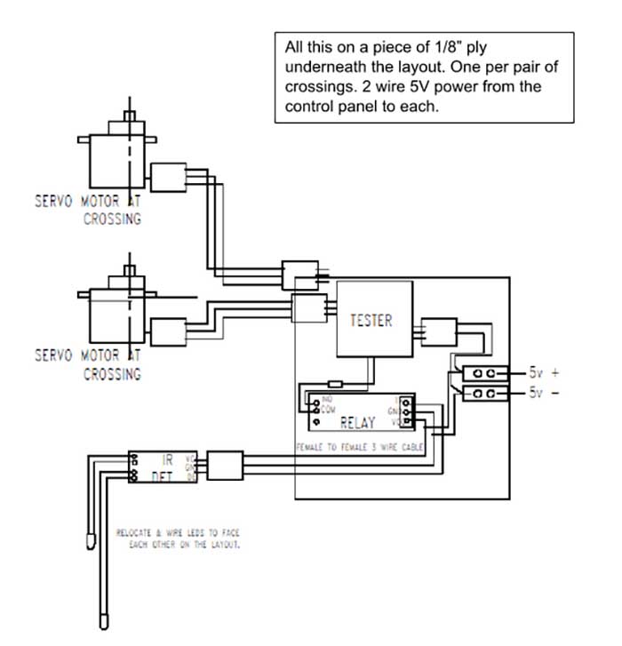
Below is a wiring diagram.
The three wires are cables made for servos and the squares are female connector ends.
The basic operation is: all servos are connected with a positive, a negative-, and a yellow signal current wire.
In this case we use the testor to provide the signal and the servo will revolve 90 deg back & forth in response to the testor input.
The IR detector senses a train then sends a signal to the relay, the relay turns the testor on or off and then the servos rotate to move the crossing gate up or down.
Each testor can work up to 3 servos and we have 2.
Model railroad crossing wiring:
This is a pic of the Servo testor. You remove the knob & blue cover and solder two wires as per the following
pics.
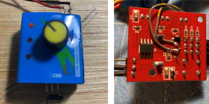
Right hand pic shows the back of testor with 2 wires soldered.
This pic is of an IR detector out of the box. We have to cut the white & dark LEDs and wire them so the bulbs will be placed on the layout facing each other, on each side of the track and hidden in the scenery.
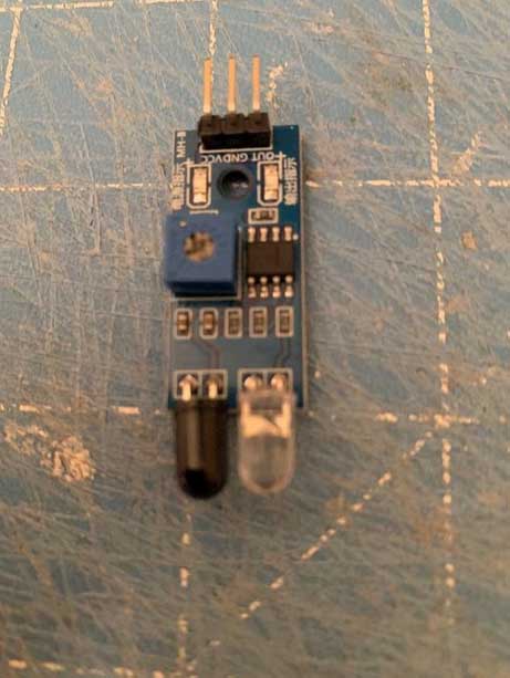
This pic shows a test rig with the rewired IR bulbs and a functioning setup.
Put 5 V dc to the TB and all devices will show lights and if you place something between the IR bulbs the servo will rotate 90 deg.
There is a micro switch attached to the servo that will turn the blinking red lights on & off. The servo arm pushes the switch arm.
There are 2 servos below and 2 crossing signals above but only one servo needs a micro switch to work the lights on both signals.
This endeavor might seem daunting but it really is not bad once you built one.
It is time consuming, tests your soldering skills, and is fiddly connecting that piano wire from the servo to the crossing signal.
Because I dabble in S scale my crossings are to scale, look right, and except for a too quick action are my answer to proper crossing signals.
Now I just have to figure how to connect a clanging sound and I’ll have it just right. The criteria is it must not be pricey.
Best
George from LI NY”
A huge big thank you to George for sharing his excellent ‘how to’ on his model railroad crossing.
As George says, some projects may look daunting, but broken down in to steps, they are too bad at all, and as George has shown, they can save you a small fortune.
There are quite a few posts on signal wiring on the blog now, and I’m pleased it’s helping a few of you out.
Here’s the post George mentions above on IR detection:
Also, these may help:
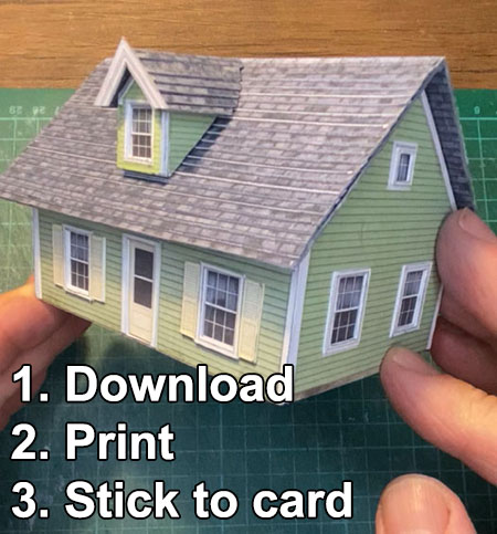
Lastly, if you’ve been eyeing up any of the new printable buidlings in the store don’t forget the coupon code carrot123 gets you 50 percent off – so you can grab them for just $3.50.
Here’s one of them being put together:
Remember, use the coupon code carrot123 to get them half price – just $3.50
That’s all for today folks.
Please do keep ’em coming.
And if today is the day you get started on your layout, the Beginner’s Guide is here.
Best
Al
PS More HO scale train layouts here if that’s your thing.

Like George, I love to keep the cost down wherever possible. I will definitely have a go at this, but with gates rather than barriers (UK, 1950s). Thanks for sharing it George.
Great article George. You might also want to check out WEHONEST on eBay. They make a huge range of electronic items for model railways in most scales including railroad crossings with lifting gates and sound. Their prices are incredibly reasonable as well.
I have no connection with them except I’ve bought and used their products in the past and found them to be reall good value.
Now this is what the hobby is about. Not timing how fast a layout can be whipped together but the journey towards that goal. Yes, some type of electronic/electrical discipline would be required and don’t underestimate China either… great way to retain your sanity through those “golden years” lmao (there also).
Very good article, Rich
A great article. Keeping the cost down but having a realistic operation is what it is all about.
Wonderful use of technology. Nothing I’ll likely try but glad you did, and shared with us!
Wouldn’t it have been easier to use a pressure plate that triggers the circuit when a train rolls over it, more analog than digital. I applaud the article and the work entailed, but seems way too many moving parts. Just a thought.
I’ve done a little programming on micro controllers and controlling servo speed and range is a snap as well as getting input from the sensor without the relay. With multiple inputs to the microcontroller you should be able to control at least one crossing with one arduino, a couple of optical sensors, servos and the leds. With some fiddling you should be able to produce sound also. There is a very large world of unexploited capabilities out there for a little work.
Once again I’m awed and amazed . Clever people you model railroaders are , clever indeed . Never ending cornucopia of ideas and imagination . Most impressive .
My fat fingers and diminished vision won’t permit me to attempt many of the great innovative ideas and techniques but that doesn’t prohibit me from understanding and appreciating your efforts and expertise as well as the dedication to the hobby y’all exhibit … thank you for sharing , it’s a marvelous solution
Wow! George is both a thinker and doer. A big part of this hobby is innovative thinking and he ( I am privileged to know George) is always seeking a better way. Well documented and explained, This is George at his very best.
Great article George! Fortunately, all of the components that you have used are inexpensive and easy to obtain. Good photos of your prototype! The schematic helps to understand the concept. I think that you might be able to use one servo for both crossing gates by adding some linkage underneath the tracks (although that would make the installation more difficult). 3D printing the signals and gates would simplify the construction process. Very creative!
There are a lot of good design and decorative improvements that can be made by slightly changing the shape of your mechanisms and by using paint and decals. Use thin sheets of basswood (either solid or as 1/8” plywood). It is much easier to work with than maple, and you can sandwich pieces to make any thickness.
A decent 3-d printer is not cheap.
A thought for George on the timing of hi crossing arm movement.
If the servo motor operates on a range of voltages, a lower voltage to it should slow it’s operation. This would slow the operation of the arm. A little experimentation would allow you to adjust the timing to your liking. Adding a potentiometer in-line with the servo power line might work for this.
Norton
George. I want to thank you for a very explanatory article that I wish more contributors would use, so this “slow” modeler can understand. Entered articles like this would help more people to try new stuff to enjoy the hobby even more ! The more detailed explanations the better. Thanks to the great AL for having such entries.
Nice George. Thks for the post. I use Light Dependant Resistors (LDR) to detect trains. Circuit is 5V — LDR1 — LDR2 (in track) —50K potentiometer —0v. The centre tap from the potentiometer is the input to Arduino (or whatever) and adjust as required. The first LDR acts as a compensator, so that if light changes, both LDR change together and the voltage divider remains fairly stable. I find this is more reliable and cheaper still!!
Steve White (Sydney)
George, Great write-up on making a train detector to drive the crossing arm servo. I assume the IR detector LEDs are some distance away from the crossing so the crossing is protected before the train arrives. Does the apparatus (IR sensor, relay, servo controller) keep the arm down until the train has passed through the crossing ? Can the outputs of two IR detector modules, one on each side of the crossing, be connected together to drive the single relay ?
Rick
I’ve tried to stay away from Arduino because I philosophically believe in keeping controls academically simple- on or off does the trick. That testor is as complicated as I want to get and it can vary the swing of the servo by adding a resistor in the wire soldered to it. I fully get your approach and many are tending to go to arduino and I will save that for another function.
Norton
Good advice- must ponder that one because it must not vary the voltage to other devices.
David
The IR LEDs are located about 6″ or so with the track in the middle, and high enough to sense the car bodies not the wheels, and at an angle so they cant sense the space between cars. When a train blocks the IR light the gates come down and stay down until the IR LEDs see each other again and then the gates go up until something else blocks the LEDs.
thanks guys
Could you attach the servo wire to a disc and another wire to the gate and create a slower motion by attaching the wires to the disc at different distances from the center?
I have just two crossings on my layout and was looking for flashing lights and IR detectors. I found them on eBay. I am modelling in N gauge but I know they are available in other gauges. This is what they are labelled as “1 set grade crossing signal + automatic controller by train detector auto flash” They have all the associated electrics and boards as well. They cost $US35 for a set. This equates to about $50 for me in the land down under, plus postage. Wehonest No. 92779. My period is before the use of boom gates. I saw that they do have them also.
keeping the costs down is always the way to go. nice article.
I was able to get the bell sound for my N-scale layout from eBay. It was not expensive, unlike my Europe-centric warning sound for my OO British layout. Also, I was able to use the bell sound for two different crossings at opposite ends of the table by placing it in the middle and using a relay to electrically isolate it from the two crossings. It worked great. I did notice the Chinese switched the red and black wires, though. They seem to use red for ground (-) and black for positive (+).
Rob McCrain
Why is your crossing on the top of a wedge of brie cheese?
I am installing two sets of crossing signals on my layout, a small N scale layout. I went online and found a Youtube video that set out the whole process using Arduino and JMRI. The whole cost of the bits and pieces from Amazon and Aliexpress was about $AU40. There are two videos covering the process with each being about 25 minutes long. They are a production of The Little Wicket Railway. Easy to follow.