Gary’s been in touch and he’s been busy with his HO scale signals:
“Hi Alastair…
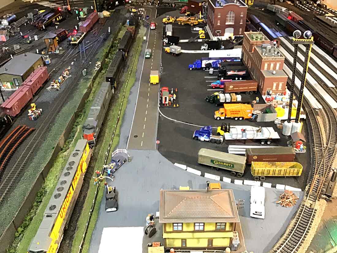
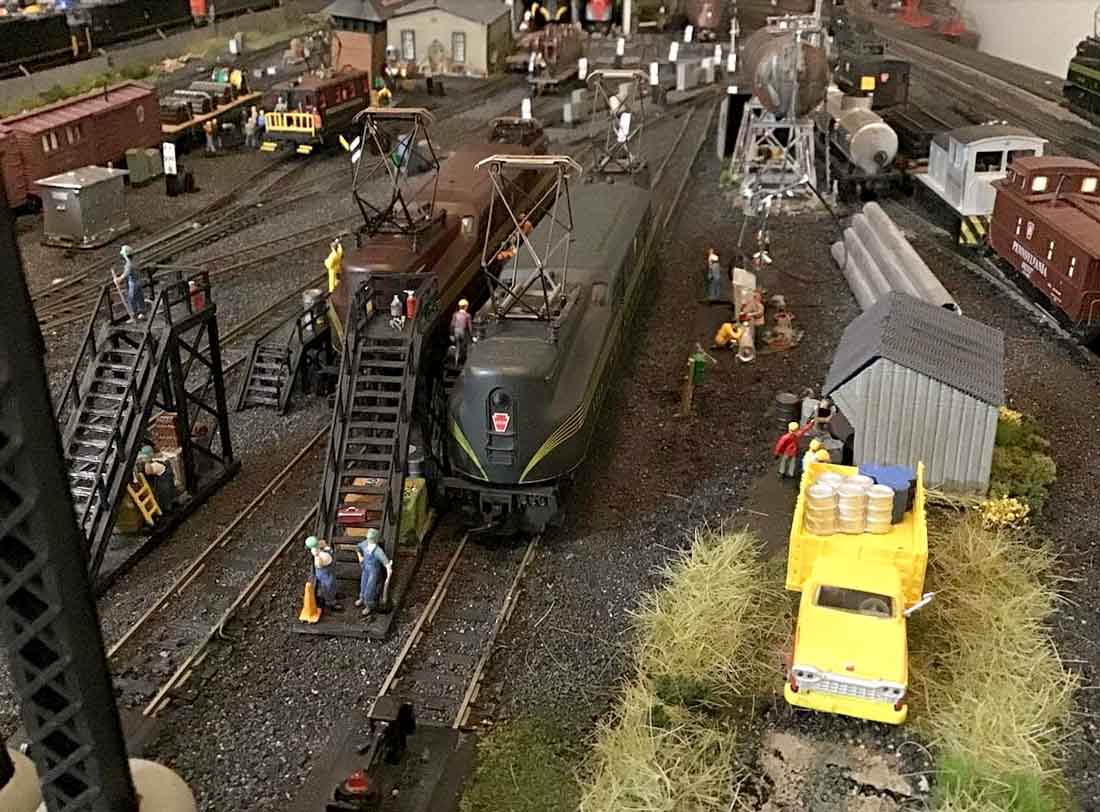
As you know my layout is a smaller model of the PRR Sunnyside Yards in Queens, New York. It is not exact but has the three main features of SunnySide which are the Passenger Yard, Commissary Building area and Engine yard. I have a double track main line running around the outside of the layout.
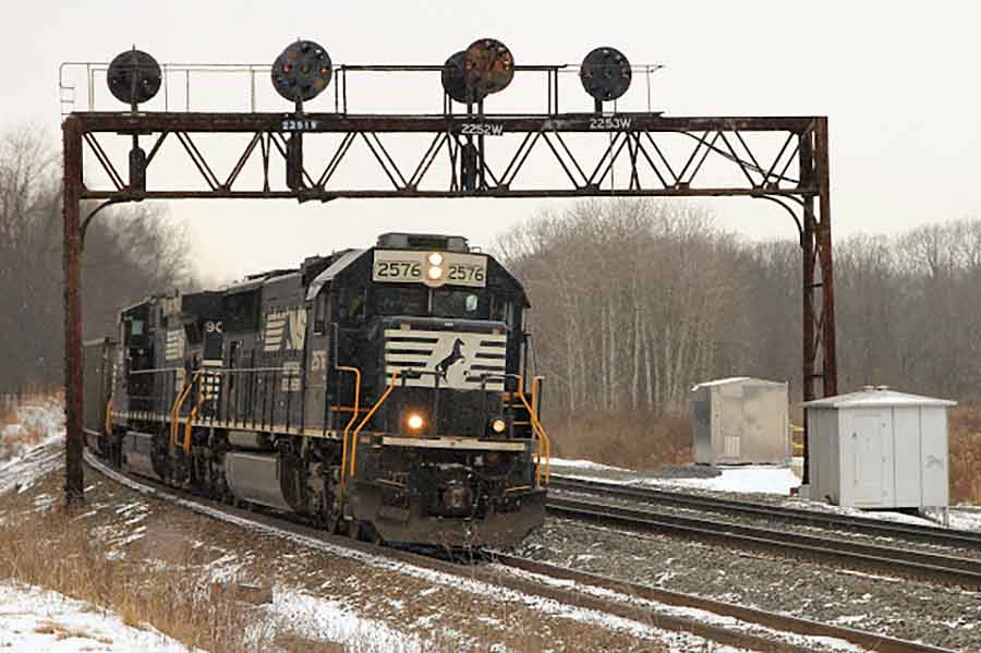
Being that my theme was the PRR, I have wanted to install PRR Main Line signals; see below for what the real signals look like.
It took me awhile to find them; the signals were hard to come by and expensive. I thought now would be a good time to start since I was limited to how much I could move around and going under the layout was out.
I decided that I would build a prototype signal first to make sure I was going to be able to do it because of the number of LEDs and wires that were going to be needed in a small area. I purchased broken signal bridges on EBAY cheap and will kit-bash the signal bridges.
My plan is to install four signal bridges like you see in the above picture. One on each side of the layout. The signals would work in conjunction with the blocks on each side of the layout.
As the power is turned off the block, the signal would be three horizonal lights, the STOP position. When the power is restored to the block for the train to proceed, the signal would switch to three vertical lights.
Signals and block power will be manually controlled at the command station through toggle switches. (I know that there are companies that have the newer technology for model railroads for doing all of this very easily, but what fun is that).
My goal was to make one working prototype of the signal.
Here is what I did.
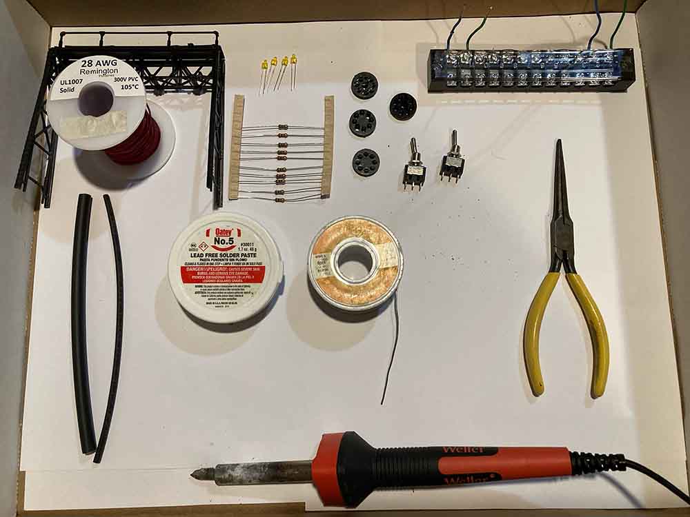
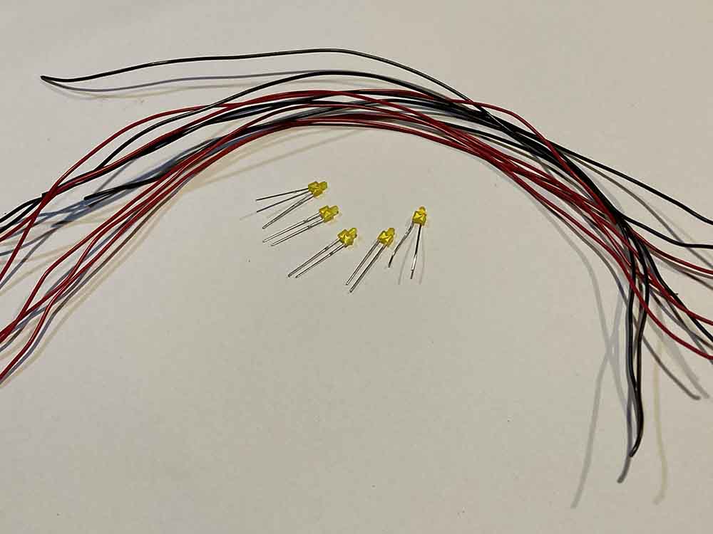
What we will need: (see Pic_1 & Pic_2)
– signal bridges
– LEDs
– wires
– heat shrink
– resistors (4K Ohm)
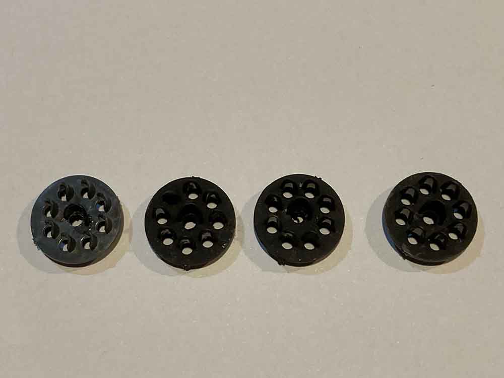
– circular signal frames
– electrical terminal block
– toggle switches
– TOOLS: wire clippers, solder and solder iron, pliers
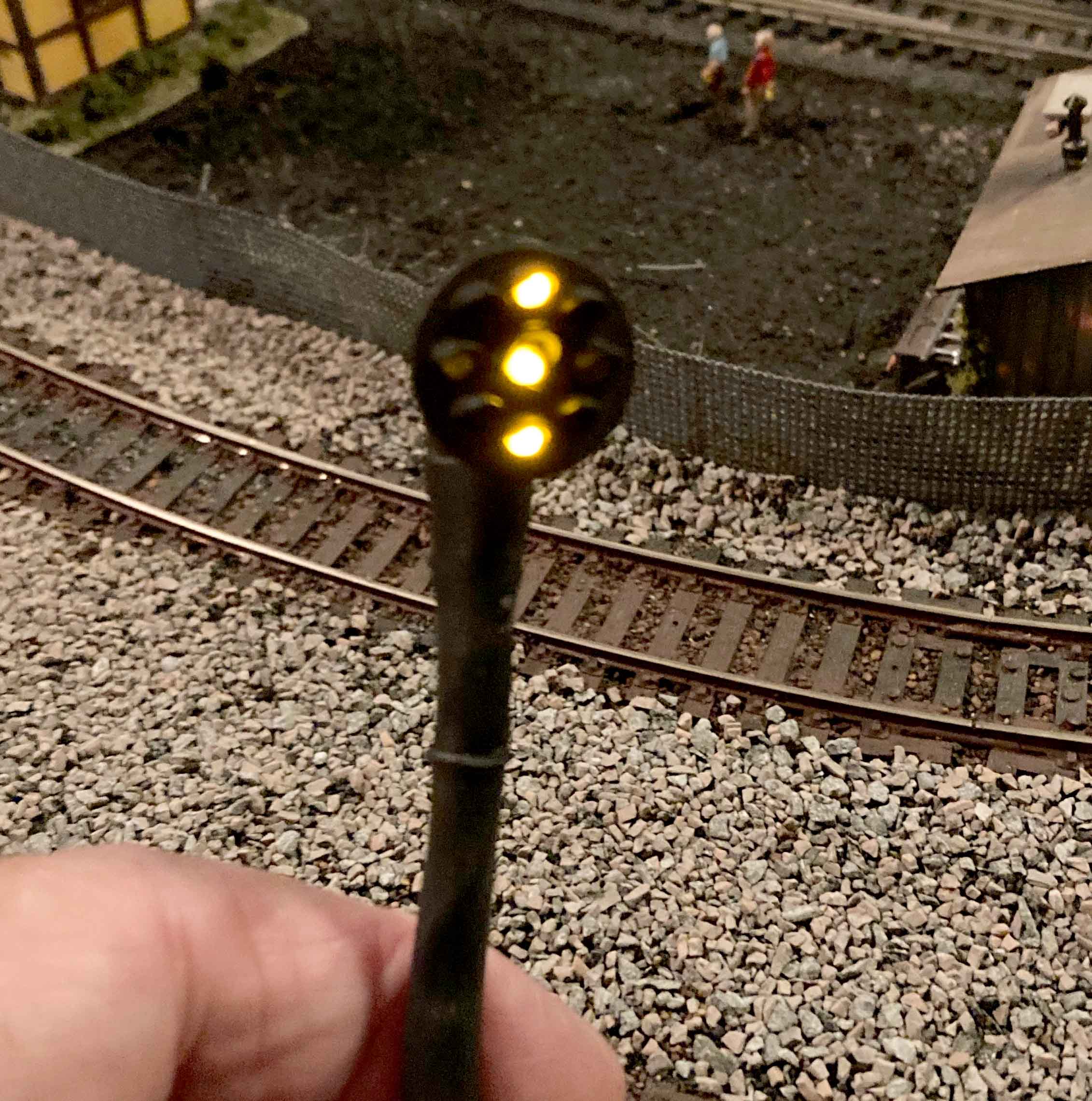
These signals will have 5 active led lamps; one in the center and one each on the top and bottom and one each on the right side and left side. That is 10 wires coming out of the back of the signal plate.
The challenge is to limit the number of wires that will have to run from the signal plate down to under the layout to be connected to the electrical power for lighting.
I decided to use solid 28 AWG gauge wire, very thin but still solid.
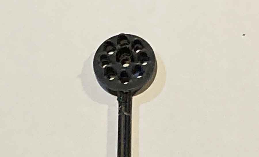
I purchased Baltimore and Ohio HO scale signal plates from a company called International Hobby Corp and had to modify the signal faces to resemble PRR signal faces.
The openings in the signal plates were enlarged to fit 2mm LEDs and I had to add an additional hole for the center light.
A lot of time was spent experimenting with the resistors sizes because I wanted to limit the intensity of the light. I did not want the LEDs to be very bright like some of the LEDs I first used in working on the layout.
I started attaching the LEDs to the signal plates. Pictures 3, 4 and 5 show what parts are going to be assembled.
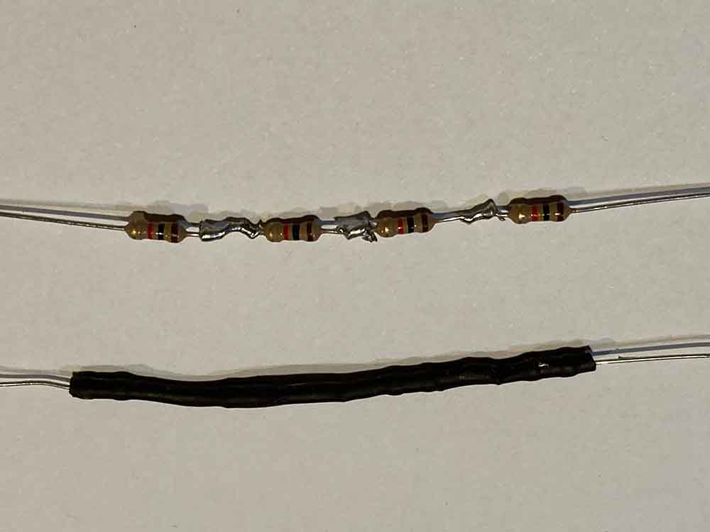
I had many 1K Ohms so I decided to use them and put them in series. I thought that 4K would be enough to evenly dim the yellow LEDs enough so they all matched in intensity but I had to use 8K for the two LEDs around the center LED which were in series and actually 12K for the center LED, which was a stand-alone LED.
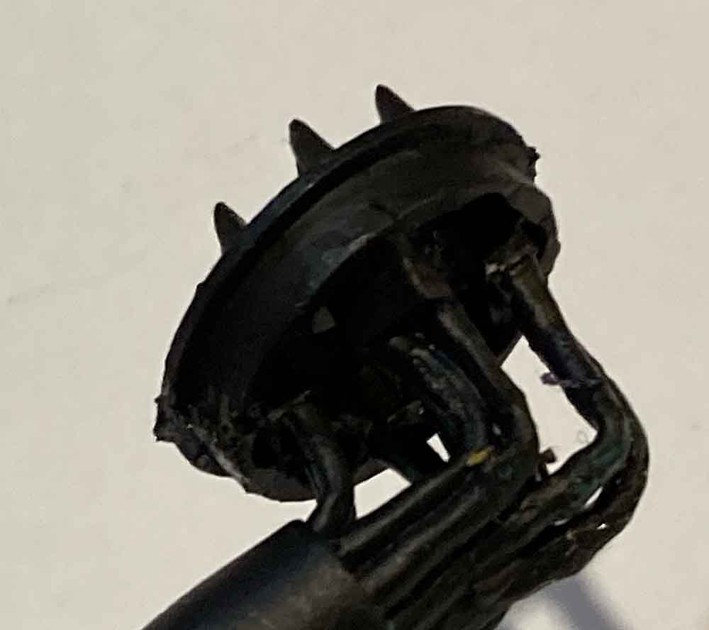
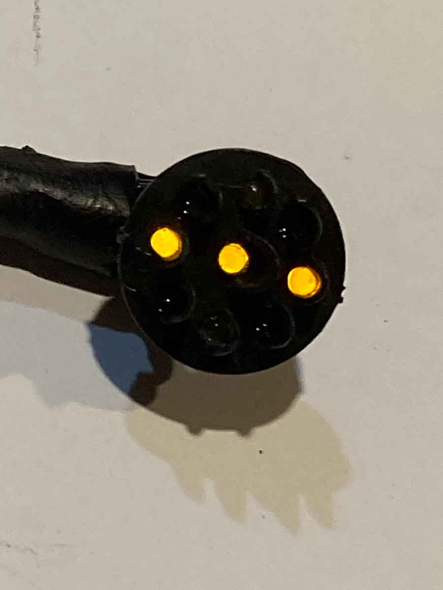
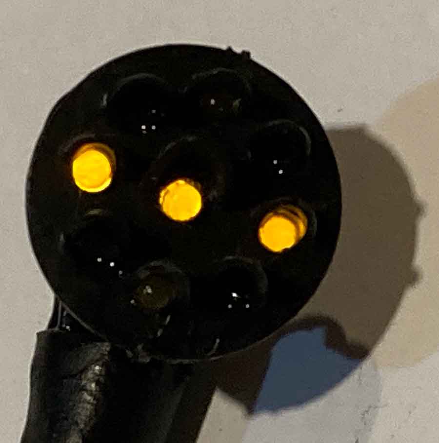
Picture 6 shows what the back of the signals looks like when each of the LEDs is installed with its power connector wire and common connector wire coming out of 5 LEDs. Pictures 7 & 8 were the testing to make sure everything to this point was working with my HO scale signals:
Next, I had the figure out how to reduce the number of wires that would run down to under the layout.
Under the layout will be a six-position terminal block connected to one of the A/C buses running under the layout. The center LED would always be lit, so its power lead and common lead need to be run down and would be connected to the first two position of the terminal block.
The two LEDs on each side of the center LED will always work together so I could connect the two power leads together and common leads together and reduce four wires down to two.
The power lead would be connected to a toggle switch from which it would draw it power and the common lead will be connected to the 4th position of the terminal block.
The same would apply to the LEDs above and below the center LED for the vertical signal. Its power lead will be connected to the same toggle switch from which it would draw its power and the common lead will be connected to the 6th position of the terminal block.
Now the number of wires running down have been reduced from 10 to 6.
The forward position of the toggle will provide power for the vertical signal (PROCEED) and the back position of the toggle for the horizontal signal (STOP).
The remaining six positions on the terminal block will be for the second signal for track 2 of the main line.
At this time, I have only completed building this one signal. It looks very sloppy because I had to retest the lighting with different resistor strengths to get the right brightness for the LEDs.
I actually soldered in series multiple 1K Ohm resistors. The center LED uses 12k Ohms. The horizontal and vertical LEDs used 8K Ohms.
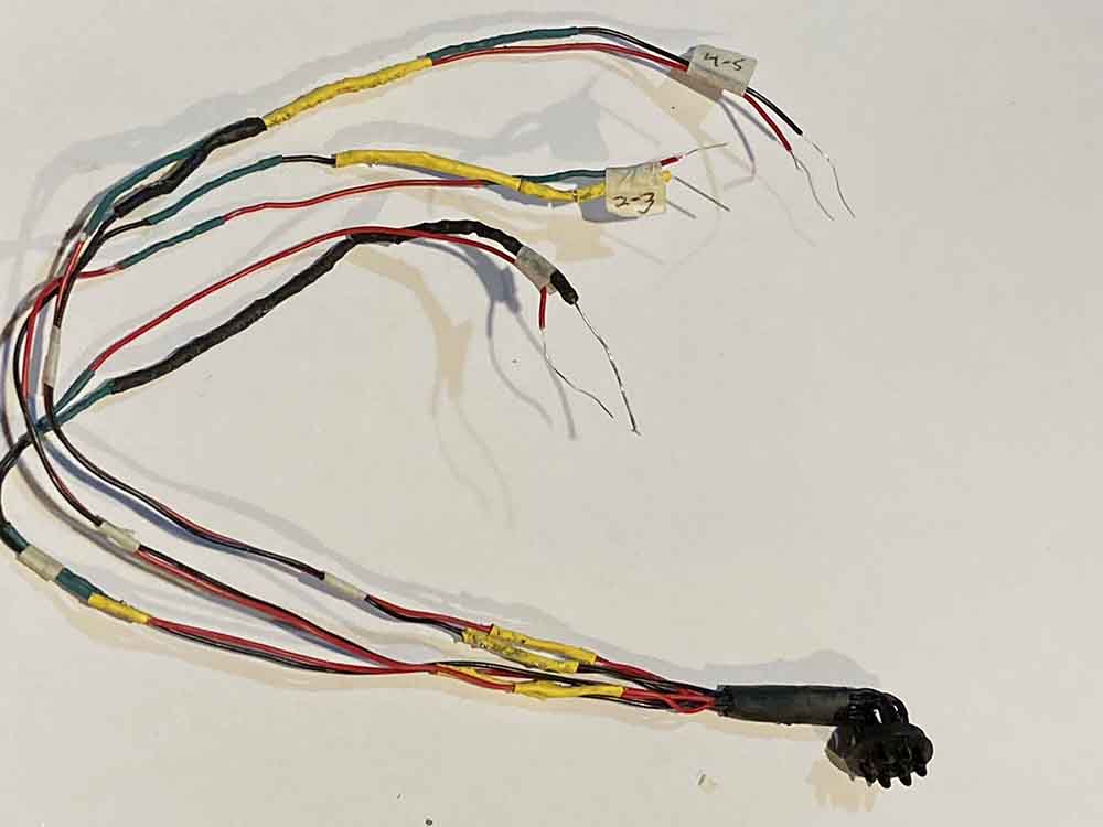
Picture 9 shows what the signal looks like when all assembled. I have labeled and numbered the wires so that I know which ones to connect to the proper positions on the terminal block. I also have to add additional black heat shrink to cover the wires running down the signal bridge.
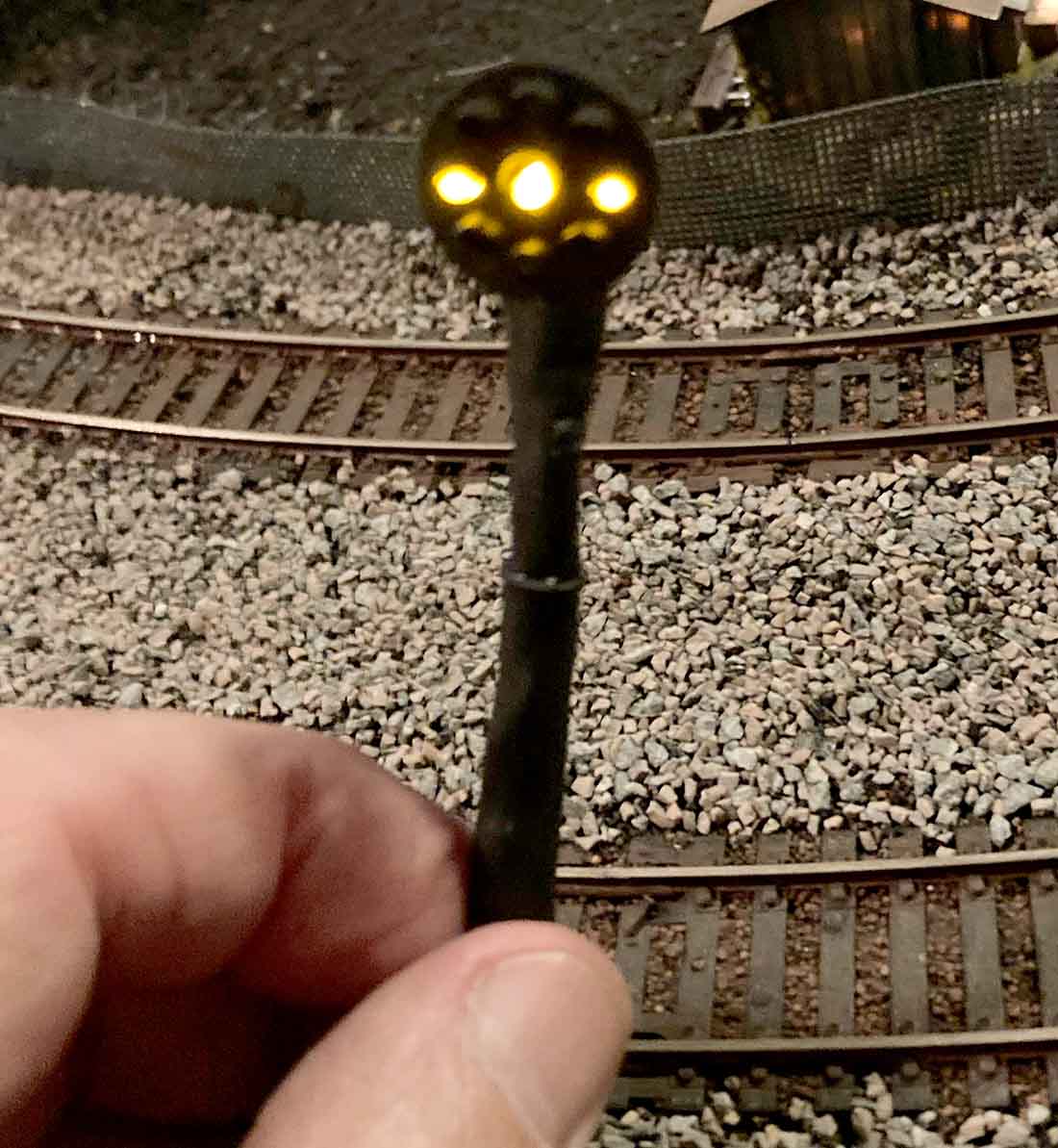
The final test of the signal was with the power from the A/C control box. Picture 10 & 11 shows a working signal ready to be mounted and installed on the signal bridge, Picture 12.
What I have remaining to do for this first main line signal bridge:
Build two more working signal with cleaner and neater wiring for main line tracks 1 and 2 for the east bound traffic.
Build two dummy signals for the west bound traffic; although on my layout there will be no trains running in that direction so the signals will always be in a STOP position.
Run all of the signal wires down the signal bridge to under the layout to connect to the power supply coming from the terminal block.
Send you a video of the finished project.
Build the remaining three signal bridges for the other sides of the layout. I have not decided whether to incorporate blocks of the remaining sides. If I do not put blocks on those tracks, the signal will just be dummy signals always lighted in one position.
What I learned and what changes I will make in building the remaining signals:
– THIS WILL TAKE A LONG TIME.
– instead of soldering 1K Ohm resistors together, I will use 5k and 3k Ohm resistors.
– if I make the holes a little bigger in the signal plates, I can use 3mm LEDs that might reduce the size the resistors I need and maybe reduce the number I need.
I will keep you posted when I have the first main line signal bridge installed and working.
Keep up the great work with your site. Its always great to see an email from you each morning. The work your members do is incredible.
Regards,
Gary M from Long Island”
A big thanks to Gary for sharing his HO scale signals missive.
I do enjoy seeing how you all come up with inventions and solutions.
Gary’s HO scale signals also reminded me of Rob’s model railway signals post.
And then there’s Henry’s Wiring signals for your model railroad.
Andrew’s How to make model railroad signals post is useful too.
What’s more, Gary has done a solid job of documenting his layout from start to finish.
I know I’m always banging on about making a start, but a close second to that it to pick a theme for your layout.
A theme really does ‘glue’ a layout together visually, and I think Gary’s is another fine example of that – he had a clear theme in mind before he lifted a finger and it’s really paying off.
Here’s his journey so far:
1. Gary starts with track work
2. Gary adds a layout signal yard
3. Gary hits a problem (it’s in the middle of this post).
4. Gary adds an engine yard
5. Gary’s Switch yard
6. Gary adds buildings to his yard.
7. Gary’s layout power problem.
8. Gary adds to the train track on his layout
9. Gary says thanks for all your help! (It’s in the middle of this one.)
10. Gary sorts his block work
11. Gary’s engine yard
12. Gary’s locomotive engines
13. Gary’s comissary yard
14. Gary’s train layout update
That’s all for today folks.
Please do keep ’em coming.
And if today is the day you get started on your layout, the Beginner’s Guide is here.
Best
Al
PS More HO scale train layouts here if that’s your thing.
Need buildings for your layout? Have a look at the Silly Discount bundle.

Gary
Much thanks for a great & thorough narrative about PRR signals.
Your layout is awesome.
Hope you stay well
Your neighbor
Wow
Wow! A well defined and articulated “how to” on building signals! These are so helpful. You showed clearly the pitfalls of such a project and how to avoid them. Thanks for taking the time to explain everything. Looking forward to the completed project!
Gary,
Excellent work! Here are a couple of considerations for any future work:
– braided/stranded wire will have more current capacity than a solid wire of the same gauge.
– Perhaps the resisters can be at the terminal strip BELOW the layout to minimize the bulk that has to be accommodated at the light bridge.
What is the minimum height the signals must be above the track surface?
For Richard J Mucked……. Is your question for my layout or for the real railroad signals? For my layout I have the signal bridge 3 3/4 inches above the tracks. For the real railroad I would think at least 15-20 feet above the track. The real engines are at least 15 feet in height.
Gary,
Common is common. Solder all the common leads together and have a single wire go down. Now you are down to 4 wires, a common and three from your three anodes. Use stranded wire, it is flexible and can carry the same amount of current, which is small. Put all the resistors under the table, they don’t need to be anywhere near the LEDs. Use black for your common, three other colors for the anode wires, then no need to put labels on the wire and you will always know what go where.
Earl from the Monterey Branch.
another wire reduction can reduce the wiring by crossing the vertical and horizontal
LED teads and control which ones lite by revering the polarity of the power to the LEDs.This way only two wires control 4 LEDs. A diode bridge off these 2 wired will
light the center LED, no matter which position the switch is in.
Gary, I am with Earl on this one use a common return to cut the number of wires. If you connect the common to the 3 signals on the gantry then that will be 1 return instead of 3 so now down to “only” 10 wires. Love the layout, glad your back, cheers Kelvin the Celt.
Nice job!!!!!!
I made a batch of PRR signals years ago in 1-1/2″ scale for the club layout, which was later torn out and then rebuilt but no sign of the signals.
I used four 5mm leds in each spot and wired it to light all 4 in daytime and only 2 at night because the intensity was too much and would blind an engineer. Wiring was a bit more complex using two common circuits for all the bulbs plus the one hot for the middle and one each for the 3 aspects.
To Earl, George and Kelvin……thank you all for the info. For right now I am going with Earl’s suggestion to keep it simple with me for the first bridge. For the next one I will experiment with George’s method. I am not that electronic savvy; but I am learning from you guys. Thank you.
Very interesting project. I built a small traffic signal for my sister to wear as a necklace (3/4″ tall) that had correctly sequenced lights on three sides. The miniaturization headaches I went through with it are similar to the ones Gary is exploring. One comment on your wiring. You should only need three leads from the signal head to your terminal board under the table. All the LEDs can be wired in two series cofigurations that will require only one resistor pack. Wire three LEDs in series and size your resistors to light them as bright as you want. One of these LEDs is the middle lamp. Use the one on the end of the series string. Take the other two LEDs and wire them in series and connect them to the already connected end of the center LED. You should end up with a “Y” with three ends. Connect the wire from the center LED to one side of power, and the other two leads to your control switch. Either way you switch, you have a three LED series connection. putting the resistor pack in series with the center LED lead simplifies your wiring immensely.
I will draw up a schematic of this configuration and send it through Al.
Charlie
Charlie…. I would love to see this schematic because you lost me half way through your write up
A few things noted, no criticism intended:
1) connect 2 wires or anything together with 2 tiny loops of either solid or tinned pieces vs twist around each other connection. Solder the loops together and heat shrink… meets both mechanical and electrical aspects, very compact. LED’s an exception or transistors of course with direct connection- bulk is everything.
2) twist wire pairs together for excess slack take-up and sorting of cables/circuits. Again will compact and looks great.
3) comb wires and cables as if actually running a comb through them before bundling or terminal connections made.
4) don’t blob soldier on connections, should see outline of connection wiring and shiny of coarse.
5) it’s about what never is seen. I don’t have a clue??? Was building aircraft wiring harnesses for Lockheed P3 Orion aircraft at 22yo, master electrician at 24yo and 38 years after settled down as electronic tech with DoD. Just sayin’ lol…. and yourself???
Regards, Rich
Most impressive, I can’t imagine working with such small stuff and it actually worked . You are determined . Thanks for sharing
Making your own signals is a rewarding thing to do. It improves your knowledge and skill set with soldering and many other things. You can learn about the needed resistance to keep an LED safe for a long life. The construction of the housing and support structure is fun too. There are many ways to do it. Try them all…
Rob
lots of work. sjows you like what you are doing. very nice job. good ideas on the wiring.
Great work on those signals Garry.
I use wire wrap insulated wire for signals.
It has the advantage of being much smaller (30 AWG) than normal hookup wire and saves a lot of space.
I got a little lost in what CH said too.
basically all your commons will be tied together at the terminal block.
then you have 2 horizontal leds tied together at terminal
and two vertical leds tied together at the block.
now here is where he lost me – sounded like tying the center
to both vert and hor, That would work, but center would be off
if neith hor. nor verrt,are on. But you said you wanted it on all the time
so would need a 4th wire to the ‘hot’ side of center led.
but yiou cold do that at your terminals and still only have 3 wires –
one for hor. and one for vert. plus one for common. Common tied to
one side of your AC and the other side to the center post of switch.
then of course the other two wires to the sides of the switch. Now lust in case you get the stop/go backwards on your panel, just rotate the switch,
don’t bother reconnecting the wires to the switch.
hope that helps
ds
(retired IT tech support supervisor)
Has anyone thought about fiber optics besides me ?? would really cut back on the clutter and to fix it you just slide under the table .
I don’t know PRR colors. There are combination red/green LED’s. They could be used in the center. Then plain red and green LED’s on the ends.
PRR did not use colored lights on signal bridges. AHM is no longer in business and they offered the correct PRR targets.
For us old folks. a wiring schematic of the recommended simplification changes would be helpful. I’m 82 and can use all the help I can get.
That is quite a construction project and the details are great and I wish you a lot of success in the work and it should be very nice when is completed.