Gary’s been back in touch. He added some HO scale engine yard buildings to his layout. It’s really taking shape now!
“Hi Alastair.
It has been seven months since I sent you the first pictures of my layout of the PRR Sunnyside Yards in Queens, New York.
At that time I had completed the first phase of my project which was the track work and signal work on the passenger yard. My next phase was completing the track work and signal work for the engine yard.
Yesterday, I finally completed the track work, switch work and signal work and blocks for the engine yard.
I don’t know if I am just slow or if it takes a long time to work on a model railroad but it took me five months to complete the engine yard. I learned a lot.
All my signals are synced up with the switches. I installed a Circuitron Auto Reverse circuit (AR-2) that controls the polarity of the tracks that my engine for my work train runs on, which you will see running in the short video.
I also installed an under table magnetic uncoupler that is on the rail right next to the two main line rails. This is so I can uncouple the GG1 engine from the passenger train, run it into the engine yard, park it on one of the spurs and run another engine out to hook up to the passenger train and then run the train out onto the main line.
I also built my first SCRATCH building, the engine house.
I lost two months’ time in June and July due to knee surgery and I could not get under the layout table. So during that time I worked on building a scratch engine house which closely resembles the engine house in Sunnyside Yard and scratch built yard lighting towers.
I had to build the engine house from scratch because I could not find any model buildings that resembled it.
Here is a picture of one the HO scale engine yard buildings; each of the doors has an overhead lamp that light that you will see in the video.
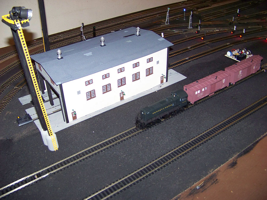
All the switches have either a dwarf signal or upright signal that is controlled with the same switch controller that throws the switch; so when the switch is heading straight, the signal will be green; when the switch is diverging, the signal will be either red or yellow depending on what color I used.
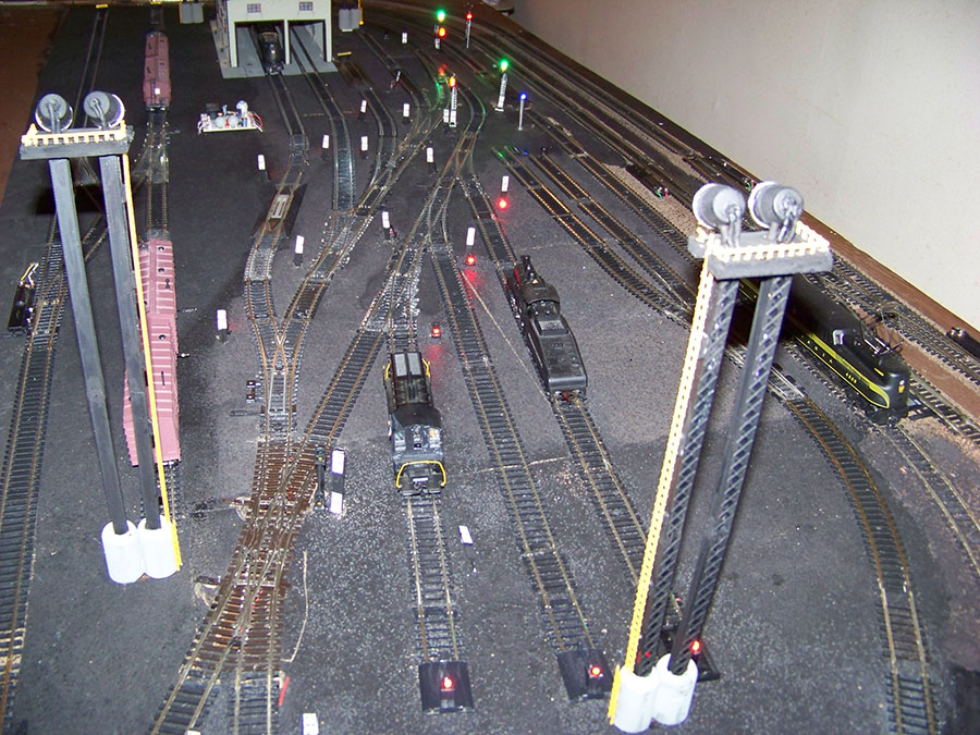
The engine yard has two main tracks going through it up to a slip switch which has a double signal (see pictures 2 and 3).
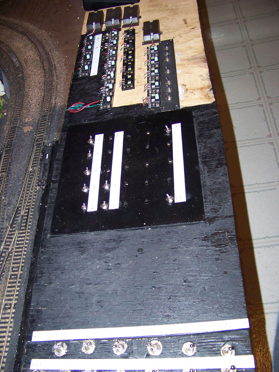
All of the seven spurs off these two tracks are blocks which have their power controlled by a toggle switch on my panel (see picture 4).
I have left a lot of space on the panel for future phases of the layout. All of the signals and switches are labeled and numbered, just like on a real railroad, and the panel toggles are labeled and numbered for the corresponding blocks and or switches. Those are the white markers you will see in the pictures.
Now that the track work is done I have to complete the following:
finish the ground work
complete the ballast
install a scene on a crew that is doing track work
install a scene for fuel and oil track for the engines
scratch build a railroad yard office to cover the Circuitron circuit
install switchman shanties throughout the yard
install electrical relay cabinets and boxes for the signals and switches
install a maintenance crew working on a GG1 engine out of the engine house
install maintenance platforms around the yard
add some ground cover around the yard
add maintenance waste and trash around the yard
add any more scenery scenes that would fitting for an engine yard
install main line crossing signals for street traffic into and out of the yard
When that is complete, here are the next phases:
add and complete to the center of the layout the commissary buildings with delivery trucks for products needed for a passenger train
add power station, yard master towers to the center of the layout
complete the center of the layout with main road for traffic, yard crews, passenger train crews and appropriate scenery details
complete the lighting for all the passenger cars
make up the trains with GG1 engines for the passenger yard
install service crews throughout the passenger yard working on the trains
Main Line improvements:
install blocks on the inner main line so that I can control trains for crossovers
install main line signal bridges over the main lines with working signals
Outside the yard:
build a garage scene in one corner of the layout
build a Harley Davidson motorcycle shop in one corner of the layout
scratch build a White Castle Hamburger restaurant in one corner of the layout (when I worked the night shift at Sunnyside Yards we always took our lunch breaks at a White Castle that was open 24 hours)
Engine Yard from the North Side:
Engine Yard from the South Side:

Panel:
Here is an overhead view of what the layout looks like now:

I know I have outlined a lot if not an enormous amount of work but I am having a ball doing this.
I welcome any suggestions from other model railroaders. As I finish each phase I will send you updates and pictures.
I also have drawings of the electrical projects I use for the layouts such as Tortoise wiring and voltage reduction. One fault I have is not knowing what resistors to use with what LEDs.
As you can see in the pictures some LEDs are brighter than others. If any of you former or current electricians out there can direct me to how I can get information on working with the intensity of the LEDs…….. I will be forever grateful.
Alastair, keep the emails coming; I enjoy reading the articles and pictures and tips you send from the other modelers.
Thank you for this opportunity.
Gary M from Long Island”
Latest ebay cheat sheet is here.
Well, I think it should be me thanking, Gary for sharing his latest missive on his HO scale engine yard buildings. What an update and what a layout. Can’t wait to see the next instalment.
If you missed Gary’s previous posts:
That’s all for today folks.
Please do keep ’em coming, and don’t forget, it you want to start – just like Gary did – the Beginner’s Guide is here.
Best
Al


WOW, great!
Gary the best description you gave here was how you are “having a ball” doing this. I am very happy for you and that reminds me once again why we do this.
Gary
Gary great layout! Can see you have a knack for the signaling side of the hobby. Track work looks great too!
hi gary; my uncle, Charles bray, worked at the sunnyside yard for years…wondered if you knew him
Very interesting layout I like it
Hi Gary: Great layout and memories. Grew up 2 blocks from the Sunnyside yards and they were massive. In the 40’s and 50’s when steam was still being used you could hear the chugging of the engines moving around the yards also the loud PA system they had to comunicate. Then there was the Railway Express facilities located along the Northern Blvd side. Loved the tall light towers, the track work and signaling . Look forward to seeing the finished work.—-Al Korzen
Dropping resistors for LEDs – generally speaking, a LED requires 2 volts at .020 amps to operate. The size of dropping resistor required depends on the voltage of the power supply you’re using. Presuming you’re using a 12 volt supply: you need to drop 10 volts across the resistor to provide 2 volts to the LED. Ohm’s Law is our friend here – E = I x R, where E is voltage, I is current and R is resistance. Solving for R we get R = E / I. Substituting in the numbers we get R = 10 / .020, which yields 500 ohms. I would use a 560 ohm resistor in this case, You also need to consider the power dissipated by the resistor: P = E x I, where P is power in watts, E is voltage and I is current. Again substituting in the numbers we get P = 10 x .02, or .2 watts. The closest stock value would be .25 watt; I would probably use a .5 watt resistor. You don’t have to be super accurate with all this. As long as you don’t exceed the maximum current rating of the LED things will work out just fine. Err on the side of caution: If you use too large a resistor, the LED will be very dim, or not shine at all because it doesn’t have enough current to operate. No biggie – just use a somewhat smaller value of resistor. On the other hand, if you use too small a resistor, the LED may be destroyed. You should be able to get specifications for the LEDs from the supplier. What you need to know is its operating current and the forward voltage drop. This information should be available from the supplier. Good luck.
To Dave Lockett:
Dave….. thank you for the info on the resistors and LEDs. I assume that you are talking about DC current. I have been using the AC current from my power supply and like I said, the issue I have is that some LEDs are more intense than others and they always seem to be a GREEN LED and some of RED LEDs. The YELLOW LEDs always seem to be the lowest intensity. I have been using resisters that are 1K ohm for all. I did that so I would not destroy the LED.
Gary M
Listen to what Dave said about the LED’s. i feel they are a little bright as shown in your video. Dropping the voltage by the 10 volts would make them not as bright. Maybe you could lower the voltage on your power supply?
Great vides and write up and go for it.
Gary
A wonderful layout developing there and obviously enjoyable. As Dave says the calculation of the dropping resistor depends on the voltage drop across the LED. Some LEDs have different voltages so the resistor needs to vary a little to keep an even brilliance.
Here is the location of a voltage chart that you might find useful.
https://i.pinimg.com/originals/9a/fe/77/9afe777f7796f0f14acb6f2781bcda35.png
Gary
I am the slow guy-not you. There are people in this group that are so talented and gifted and their work shows it. Your work shows your talent and you must persevere with your wish list one at a time. I cant believe you did what you did and with knee surgery!! Just to be funny- I ask what’s it going to be- kerosene pots or steam ? Please keep us updated on what you do.
Thanks a mill
George from NY
Gary:
Yes, all the calculations are based on dc voltage. However, unless you’re using bipolar LEDs, the LED will only be active on 1/2 of the AC cycle; the other half of the cycle will reverse bias the LED and it will not be active. So, with AC voltage applied your LEDs are actually blinking at a rate of 30 times per second (that’s for the US; in the UK I believe the AC is 50 Hz, so the LEDs would blink at a rate of 25 times per second). No matter. If your LEDs are too bright, increase the value of the dropping resistor. Since you’re using 1K resistors, try 1.2K or 1.5K; just keep increasing the resistance until it looks right. If they’re too dim things are a little trickier; stock values for resistors below 1K are limited. DigiKey shows 910, 820, 750, 680, 620 and so on. Start with 910 and then move down from there until it looks right. I would recommend metering the current while doing this; don’t exceed 20 milliamps. If you don’t have a digital multimeter, they are available in the US at Harbor Freight (or similar stores) for around 5 dollars, or free with another purchase, if you have a coupon.
The question I have is where do you find the Dware signals or did you make them.
I am just setting up my switches and would like to have Lights at each one.
For B K Stecklein:
I purchased the dwarf signals on ebay from seller evemodel_usa.
The purchase includes 10 dwarf signals with the 10 resistors and with 10 RED and 10 GREEN leds.
They also have 3 aspect signals which I have used for the in switches to the passenger yard. I am going to use them for my main line signal bridges.
Good Luck.
Gary M
For Dave Lockett:
Thanks for the additional information on the LED lighting. I never thought of increasing the resistors to 1.2K or 1.5K. I also think that I could daisy chain two lower ohm resistors.
What is odd is that I always test them before installing and they never seemed to be brighter.
Again, thanks for the info.
Gary M.
For George from NY:
What did you mean when you asked ” what’s it going to be- kerosene pots or steam” ?
Gary M
Well geez Gary. What is your hold up? Excuses, excuses!
And before anyone jumps down my throat, this is strictly a joke1
Great job
Gary; I now live in South Mississippi, but was born and raised in New York City. I am now 89. When I was around 14, my friend and I used to ride our bikes down to the Sunnyside yards to watch all the train action from the viaduct. I imagine things have changed quite a lot since then. I can still remember standing next to the tracks near Jamaica station (around 156th street) and watch the DD-1’s roar past. They would rock back and forth when watching them head on. Are you old enough to remember the DD-1’s? I had been out of model railroading for a long time, but started a new layout 4 years ago. This time I’m using Marklin, but in a U.S. environment. (It’s my railroad, so I can do whatever I like.).