Gary’s been in touch with his HO scale wiring block.
If you missed his earlier posts, here’s the first, and here’s the second.
“Hi Alastair…. Gary from Elmont, NY, USA, here with an interim update on my Sunnyside Yard project.
My last blog to you was that I had completed the track work for the passenger yard and was going to start planning for the engine yard.
My steps are still the same and that is to complete all the track work, switches and signals before working on any scenery.
Picture 1 that I sent was the layout plan that I designed using SCARM but that did not work out because I did not have enough room because the radius of the turn track I need to use for the long engines, GG1s, and passenger cars has to be at a minimum of 22 degrees.
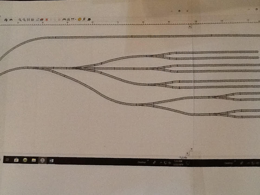
I am using 24 degree as much as possible. So I had to redesign the engine yard. Picture 2 is what I designed in order to fit within the 7 foot length that I had to work with.
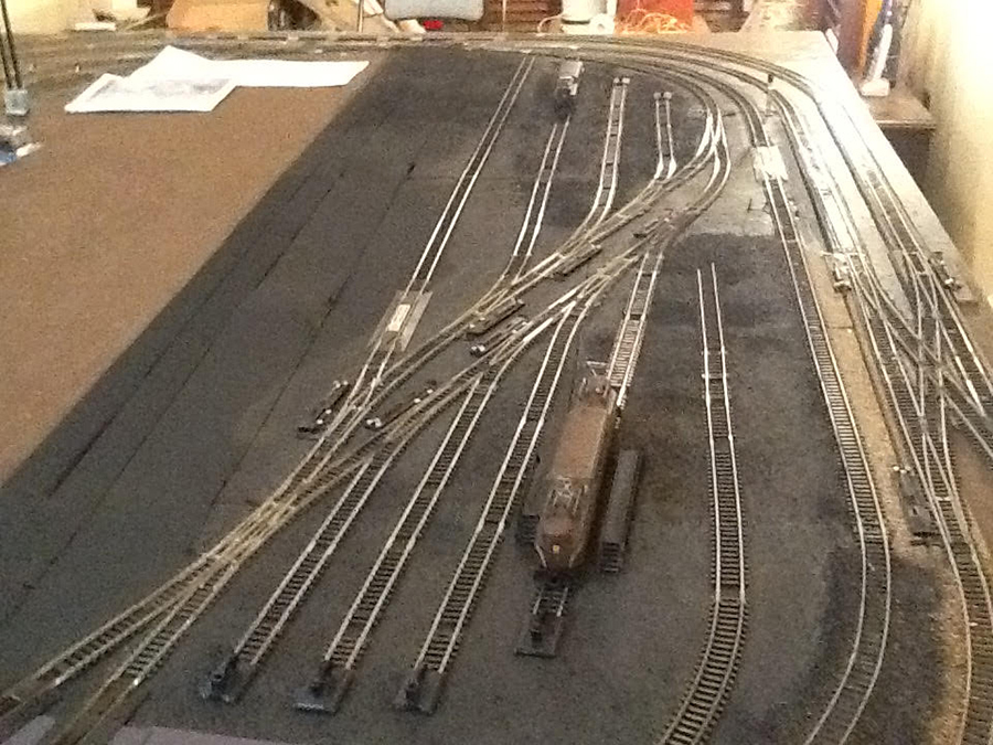
Nothing in these pictures is permanent and the few structures and trackside scenery are only temporary to give me some ideas on how it would look.
The tracks are laid down with temporary rail spikes. This actually worked out better than using SCARM because now I know that this design will fit.
I tested each above table switch machine to make sure they worked. I will be using Tortoise and Atlas under table switch machines for the rest of the turnouts.
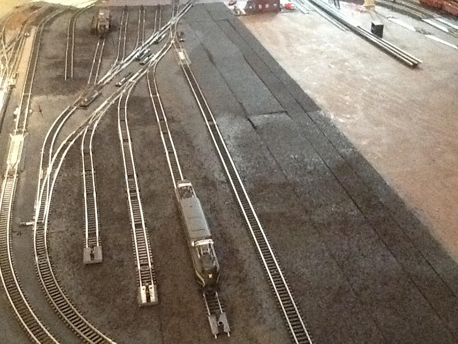
Pictures 3 & 4 I will print out and use to plan my wiring for all the blocks, switches and signals.
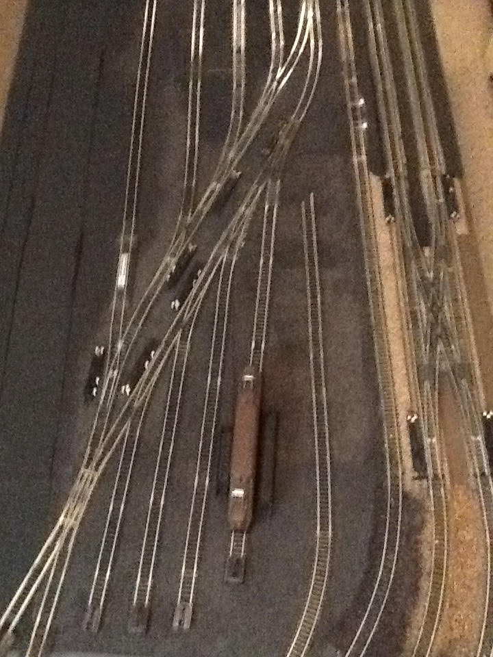
I am not using DCC so I needed to develop induvial 13 inch blocks for each engine. If you look at PICTURE 5 closely you can see where I used insulated rail joiners to create the blocks.
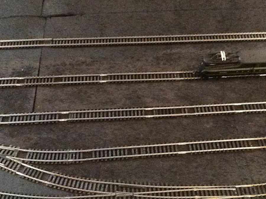
All told I have 16 small 13 inch blocks; each can hold a long GG1 engine. I also will have two work trains. If you go back and look PICTURE 2, the track to the right of the GG1 in the forefront of the picture is no complete on purpose. This is a dummy track that I am going to use to have a track crew working on the rail, to connect it up.
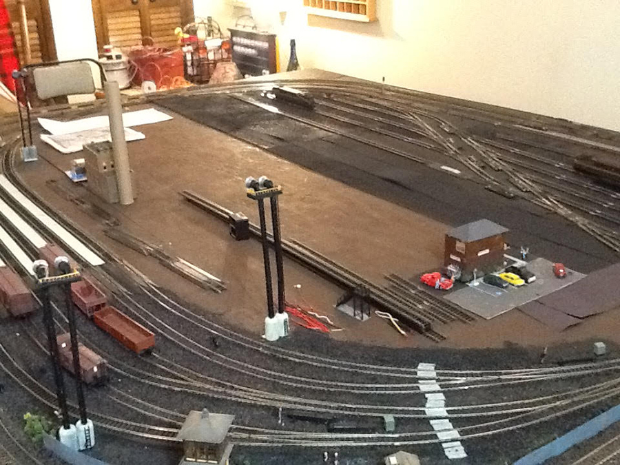
In PICTURE 2 again, you will see the SLIP Switch in the left hand corner that I am using to give any engine the ability to access and be parked in any of the yard sidings.
PICTURE 6 is what the layout looks like right now before I start working on the electrical wiring for the engine yard.
I am leaning towards have this engine yard be its own block section with a separate power supply and have a control panel catty-corner in the layout to the passenger yard control panel.
Each block will be controlled with a DPDT toggle which will control the power to the block and the changing of the dwarf signal from RED to Green when the power is on and Green to Red when the power is off.
I know that I can use the Tortoise and Atlas switch machines be able to throw the switch and change the color of the signal indicating the direction of the turnout. I would like to also be able to control power to certain blocks when a switch is thrown. I do not know if I can throw the switch, change the signal and provide power to the block that the engine is leaving. I will be calling Circuitron to talk to their tech people to find out if that is possible and how to do the wiring.
Hooking up the power to control a block is not a problem……doing it for 16 small blocks might be a wiring nightmare?
In my last blog, I received many suggestions from many of the readers……. If anyone has suggestions on the wiring, please don’t hesitate to comment. One question….is it better to use a Power Distribution board or Terminal Blocks?
Once I complete the track work for this section, I can then start on the scenery and figures for the engine yard. I am planning a two stall engine house with maintenance crews; a track crew working on completing a section of track; a road maintenance crew; some maintenance sheds and maintenance crews. Then I will go back to the passenger yard.
Am I crazy doing this because I love it. But I think I am going to be here a long time.
Keep you posted and I love reading and looking at all your layouts.
Gary”
A huge thanks to Gary for sharing his HO scale wiring block. If you can help out with his questions, please do leave a comment below.
It’s so wonderful seeing all your layouts take shape from the very beginning – especially with a good narrative too. And I know it inspires a lot of readers too, so please do keep ’em coming.
That’s all for today folks.
Please do keep ’em coming.
And if today is the day you get started on your layout, the Beginner’s Guide is here.
Best
Al
PS Latest ebay cheat sheet is here.
PPS More HO scale train layouts here if that’s your thing.


Why are you considering using DC. Do you have old engines to use? If you are starting out fresh you should go with DCC. The way you are planning using all those blocks you are going be some busy guy and not even enjoying your layout, besides the wiring nightmare.
Gary: I had the same problem with radius curves that you encountered. I have always built with 18 degree radius because you can get much more track in a confined space. I completed the Damn-it 2 Railroad and then bought a complete set of SP’s Daylight train which has 2 and 3 car articulated units. I always wanted this set and it wasn’t until they arrived that I read the fine print and found a minimum of 22 degree radius was required.
To solve my problem I created Damn-it 3 using a combination of 18 and 22 degree curves. I found that if every other curve section was a 22, the long cars & engine worked fine.
As far as SCARM goes–this may be the greatest rr program ever created–simple to use and very accurate.
I’ve always worked in DC with lots of blocks and they can be a hassle to wire & install. I have had several layouts where whole sections of the layout were wired to a stand-alone controller. This worked fine if you have more than one operator, but working solo, it’s a pain to leave the main control panel and walk over to the separate one, run that section by itself while keeping an eye on what’s happening on the mainline, and then rush back to the main panel for the rest of the layout.
Good luck on your project and keep us posted.
Terry/Idaho USA
Your yard tracks are unnecessarily far apart. Don’t be afraid to trim the ends of turnouts, particularly the straight parts, to bring tracks closer together. This’ll give you room for more sidings and a more prototype appearance.
If at all possible go to DCC.
The added cost will be well worth it. You will be running trains instead of playing with a whole lot of wire….. with DCC you can control your switches as well as your engines
When all else fails look to you tube. Also go DCC. You can go both DC and DCC by use of a toggle switch.
I am using TAM Valley for my layout and I know that the Remote 5V DPDT Relay with Y Cable for Controller Socket would work to power sections based on whether the switch was straight or thrown to the siding. I am using one side of the Relay to control a Lights at the siding, but there is a second side of the Relay that would allow the power to flow there as well.
Sorry, but personally I find DCC overrated. But then, I enjoy wiring!
I agree with all of the recommendations above — GO DCC. If the decision was based on old DC locomotives it doesn’t matter. Just add a sound card to your old locos. All DCC locomotives actually run on DC. The DCC loco card converts the DCC signal from a square wave AC signal to DC for the motor. Sound cards bring so much more enjoyment to model railroading than just running a train around a layout with no sound.
Also if you have old locos, it is cheaper to add sound cards then buying new motive power.
Hi Gary
Looks like a great layout. Well done so far!
I’m not going to get into the DC / DCC debate, but I’d say use what you are most comfortable with.
The wiring isn’t a nightmare at all if you are methodical. There’s just lots of it.
Start by numbering each feed (I marked up a SCARM printout) and use as many different colours as you can. Log the colours against the feed numbers and label each end of each feed with its number.
Connect them up and test them one at a time (use a multimeter or battery and bulb for continuity) and it’s easy. It’s the “one bite at a time” approach to eating an elephant and it worked for me.
I’ve used RS232 parallel male / female computer cables, cut with one short end for your panel and the long tail for the track. Strip off as much of the outer sheath as you need to for your connections to the track sections and cut them to length. You get about 30 connections of different colours, plus a common return and if you mount one connector on your panel, it is pluggable so disconnection is easy. Log your PIN numbers with your feed numbers and you have a complete record of what does what and where it is so future troubleshooting is easy.
Colour codes and PIN numbers are available on line, so you can add these to your schedule of feed numbers
I use adhesive labels To tag the cables. Cut into strips with the feed number at each end, then fold it over the feed wire and stitch it to itself. Cheap and easy
Good work and good luck. I hope this helps
John B
I am old school like you DC here is a thought for you try looking for a turn table and a round house to put your locomotives in if the loco are to long for the table make a siding and the big one that do not fit the table down it every thing that fits in the round house . I know I had a big boy and a cab forward thay were to big for the table, and I think it will make your lay out look a lot cleaner for the space you have
Hi
I agree with the comment about trimming the turnouts to get the parallel tracks closer together and more prototypical, you’ll get longer sidings and a more aesthetically pleasing layout too.
Secondly, DCC is a solution but the cost of decoders for everything could be higher than DC.
Third point, to simplify the D.C. wiring for the turnout motors, signals and block power……. Have you considered using diode matrices? You can then use one switch to select a complete route and set every switch motor, signal and block power on one go. This will simplify the wiring immensely. I use this for my own engine shed and carriage sidings area so that all the routes can be set by one switch per route.
Regards
Mal
North Wales
Damned, how did this model rail road thing get started with out sound? Well it must have worked without sound. DCC is good, but I am OLD SCHOOLED and for me I like the wiring and all the things you have to do to make the loco go around and and all that stuff, as in lots of things to put in the correct position to make it all work. The best part is, well it is cheaper and I don’t have to ask a friend, or pay, to have someone make it work when it takes a s**T Just Saying
NV BOB
Now all you need is the Flushing Subway Elevated Line traversing the yard.
Great job!
Re DC / DCC debate
Consider another option. Go DC or DCC (Ether. Does not matter. DC is cheaper.) with REMOTE engine controllers!
I’ve got some radio remote control engines. Controllers came with the engines. (Seems no longer made!) There’s WiFi control decoders around. And now Bluetooth (a different WiFi). They work with free mobile phone apps. Otherwise a DCC unit if you power with DCC – which isn’t necessary but might add extra features.
Kids love being able to use a hand held wireless engine controller. That includes this kid too!
Then you can control each engine INDIVIDUALLY on either power source (yours, your friends, a club, etc) WITHOUT blocks / sections.
I’ll still be wiring up blocks / sections because my Viessmann Commander will auto stop trains running into each other on the mainlines.
My remote controlled engines work with DC, DCC, supplied remote, wired DCC unit control and with blocks. New Bluetooth ones work with free mobile phone apps!
If you want to stack a heap of engines on the one siding track, I’d say individual remote controlled engines is the way to go. That way you can stack them as close or as far apart as you like without worrying about the size of blocks. Eg 3 big ones or six little ones. Just like real life. If you want to, just block the siding itself as one block! Not necessary for engine control but switching off power to a siding is always a safe thing to do when an engine/s is not in use.
Yes, you will need appropriate decoders. May not cheap atm.
No, you don’t need expensive DCC power. Cheap DC power will do.
Remember, especially for remote control engines, they can still be alive and draw power when stopped, unless you power them down. Blocking and switching off track power to a siding is a peace of mind thing and avoid accidently overheating engines or involving them in a power surge or short out.