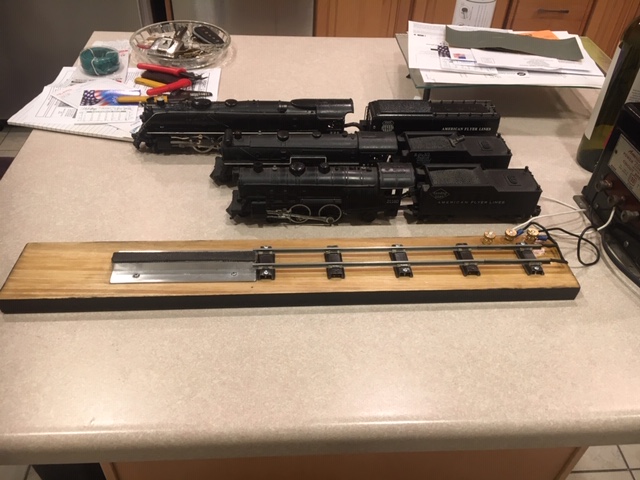
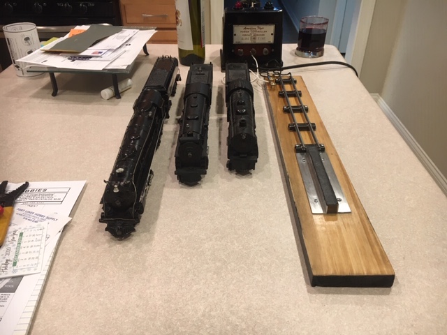
Rusty has shared the model train roller test stand he built:
“I have used several test stands and have had issues with most of them.
I made this in an afternoon for under $20. It has no moving parts, no adjustments needed.
It is a stable platform and works on any size locomotive.
Kind Regards
Rusty”
Latest ebay cheat sheet is here.
Now on to Gary. He’s made a fantastic contribution to blog with his posts (his last one is here).
But now, we can help him. He’s got a question:
“Hi Alastair…… I need some help with electronics…… here’s my problem:
I am trying to lower the voltage to my LEDs to dim them in my signals.
If I attach a 1K OHM resister to the positive side of the LED and connect it to a small 3 volt battery, the LED is dimmer then a LED attached to the same battery but without a resister.
One of the model railroaders who saw my engine yard layout, responded to my query about LEDs and resistors by saying to use a higher OHM resistor.
What I tried was daisy chaining a 1K OHM and a .5K OHM together. I put it on my multimeter and it registered 1.5K OHM….. great right?
When I attached the LED with the combined resistors to the same 3 volt battery…THE LED WAS BRIGHTER!!!
I do not understand that. Can anyone out there explain this to me?
Gary”
That’s all for today folks. Who can help Gary? Please leave a comment at the bottom of the page if you can.
And thanks to Rusty too for sharing his model train roller test stand. The simple ideas are always the best ones.
And don’t forget the Beginner’s Guide if you want to get going on your very own layout.
Best
Al


Hi Gary, Did you connect the 2 resister in sequence? Or parallel?
That makes quite a difference.
In parallel, the total resistance is much lower than in sequence.
Regards,
Ruud
@Rusty, that’s a great little to there, well done!
@Gary – can you send a photo of your connection? When you say you daisy chained the resistors, do you mean a series connection, or parallel? If it’s parallel, it will reduce the equivalent resistor of the combination, not increase it.
Roud is correct, if you wire resistors in parallel, you half the total.
Mike S
Rusty
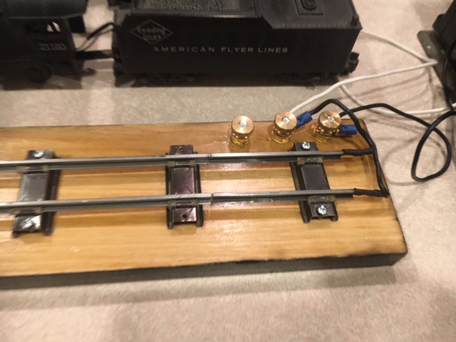
Comment is for clarity for those who might be confused. Neat setup for S scale, old style American flyer engines that get power from the tender. For all other types that get power from the engine itself you have to re-engineer the rig.
Gary
I think Ruud has it right.
Best
George from NY
I think Ruud meant connected in ‘series’, not sequence.
This a great test stand for American Flyer steam locos that get their power from the tender pick ups. The track is S gauge.
This test stand would not work for american flyer diesels,
The test stand would not work for Lionel traisnas they get their power thru the loco wheels and a center rail roller pick-up.
But it works great for S gauge American flyer which is what he has no doubt.
This is probably more info than anyone wants about LEDS but here goes anyway.
LEDS are current devices. The more current the brighter, with about a .02a max. Most will drop about 1.2vdc so the resistor needed to get the desired brightness is.
(V-1.2)/A
V is the supply voltage [12vdc-1.2]=10.8v
A is the desired current [.02=full bright, .01=half bright]
So if you are using 3 AA batteries for 4.5v and you want the led half bright (.01) the resistor should be 330ohms
(4.5-1.2)/.01=330.
You can power multiple LEDs in parallel with one resistor but the current would be additive. Three LEDs in parallel at full brightness would be 3×.02 or .06a. So the above example with 3 LEDs would be 110ohms.
I hope this helps
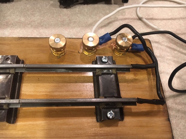
Rusty, Nice Pics but, I dont understand the wiring… What is the white wire for??
Agree mostly with Craig except that LEDs are semiconductor devices and will work if connected in parrallel but it’s better to add the 330 ohm resistor to each led. The VLed is not an exact number and unfortunately the led with the lowest voltage will take more current. Secondly it’s never a good idea to connect an led directly to a power source. The led may have an over current protection feature which is why it appears dimmer. Most leds will be damaged without that current limiting resister.
Brighter LED with more resistance. Not theoretically possible.
Ohms law V=IR and the previous calculations show that the higher the resistance the lower the current.
Now the most likely outcome is either
A) you connected the resistors in parallel to create a lower resistance.
B) you connected the resistors across ( in parallel with) the LED not in series with it. Hence in the 1k example a large leakage current and by increasing the resistance less leakage and more through the LED.
C) Dirty connection when you were messing with the 1K on its own and a much cleaner connection with the two together. Contact resistance could have been greater than the 0.5k you subsequently added, thus clouding in the result by giving a much higher effective resistance.
D) different battery? Was one on its last legs?
Finally, although the half brightness calculation works for exactly half current etc. The LEDs do not appear half brighter due to the way the human eye works so you will need to reduce the current significantly e.g <5mA to start to see truly perceivable brightness variations.
Regards
Mal
North Wales
To RUUD, KAUSTAV,MIKE,KEVIN & CRAIG….thank you for responding. I set up the resistors in SERIES. I did not know how to insert a picture or diagram. I will try to explain how I set this up:
Positive pole from 3 volt battery soldered to 1k ohm resistor which was soldered to a .5k ohm resistor which was soldered to the LONG lead on the LED. The short lead from the LED was soldered to the wire going to the negative pole of the 3V battery.
Thanks for your help.
Gary M
Craig’s formula is correct. However each LED type, especially where color or emitted spectrum is involved, has a different voltage threshold at the full-bright current of 20ma. For example, blue, green and white LEDs typically will need between 3.1 to 3.4 volts DC to draw that much current, and others, like red and amber, are usually between 1.9 and 2.2 volts, thus requiring differing resistor values. With a 5volt supply, red and amber will be full brightness with a 150-ohm resistor in series, while the blue, green and white will be fully bright with a 100-ohm resistor.
I believe Craig has said it nicely and concise. the 1.5k ohm resistor of two in series will only dim the light. Those resistor have to be in parallel to get the response reported of being brighter.
The only additional comment that I would add is that the forward voltage of the LED for different colors may be higher than the 1.2 mentioned. To get an equal brightness between red, yellow and green (most signal used LEDs), you may have to have different resistor values for each color. There should be a data sheet that will tell you the forward voltage drop.
Bob,
The 2 black wires with the terminal ends are going to the track. The other white and black wires are coming from the transformer.
The problem is with the battery. Dry cells have an internal resistance which limits their current delivery capacity – the smaller the cell, the lower its current rating, also with ageing the internal series resistance increases. This is used in LED torches rather than separate current limiting resistors. The power supply for locomotives and/or auxiliary circuits has much less impedance and requires a limiting resistor for each LED, just use the formula to calculate its value; it’s based on Ohm’s Law.
Just an aside comment: A resistor can become a battery and/or capacitor. While an electronics tech in the US Coast Guard working on a LORAN timer/monitor, part of the circuit had a small increase in voltage where it should not have had one. After hours of searching and testing we found a large ohm resistor that had cracked in half an was producing the excess voltage.
I’m going to work on this idea, I will have to change a few things around, but the idea is as good as any. I run Marklin HO AC, there is no reason why this won’t work with a few tweets.
LED brightness is controlled by current through the LED not the voltage. So to control the brightness the resistor in series with the LED needs to be changed in value. You may want to try different values of resistance to get what you want in brightness. Ohms law is involved in determining the value. A resistor value box is helpful. There should always be a resistor attached to your LED to limit current. If you don’t use a resistor you risk burning out the LED fast.
While it is correct the LED brightness is related to current, the relationship is not linear (but it is monotonic)
One question, did you change the battery when you added the 0.5K resistor. The only reason the LED will be brighter is when the source voltage changed.
Rusty,
Great job on the test stand. I, too, have A.F. trains that my granddad bought when I was about 6 months old (I’m 72 yrs old now), and they’re still running! I’m in the process of rebuilding the simple 4×8 layout that Granddad had and put up every Christmas when I was a boy.
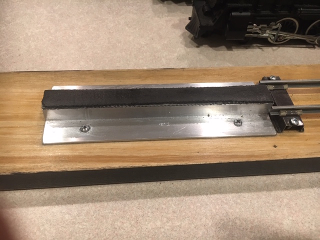
Would you be able/willing to list/explain more details of how you built the “stand” portion of your test stand? From the pictures, I can’t tell exactly how it’s constructed or what it’s composed of. Perhaps a list of materials and dimensions would be helpful.
Anyway, great idea and great job! Keep up the good work, man.
Best,
Steve C.
(Quote from Granddad – “…REAL trains and tracks don’t have 3 rails!”. That was his reasoning when he bought American Flyer instead of Lionel. Lol )
Thanks Rusty! Nice, simple solution for us S Scale folks…(76 and still railroading…)
Dennis Flyer4ever
hi gary, 1st in a 1.5k ohm series LED on a 3 volt circuit, the LED will light but probably so dim as to be seen only in a dark room. I think you may have misread the resistors as the correct range should be 75 to 150 ohms, no k.
2nd when you connect an LED across the battery, you are completely dependent on the battery to limit current, and you can see a range of light from none, to dim, to normal, to bright, really bright and burned out.
Lastly, LEDs are diodes and a small change in voltage results in a very big change in current. Also, there are normal and high bright LEDs available and the color of the LED changes the breakover voltage.
I congratulate every person that responded. Electricity can be nerve racking. I have a question that I hope one of you could answer.
I have American Flyer trains. I was wondering how to hook up the TOP ELECTRIC CONTACTS on my diesel engine.
I’m not that into electronics, that’s why I’m asking.
Happy Holidays