Paul’s been back in touch with his model train lift bridge:
Not long he sent in pics of his Chickadee Hollow railroad. You can see it here if you want to get up to speed.
This time, Paul walks us through his clever removable bridge:
“Al,
This concept shown can be adapted to any type of bridge that you want to be removable, yet adjustable, while providing access to your layout.
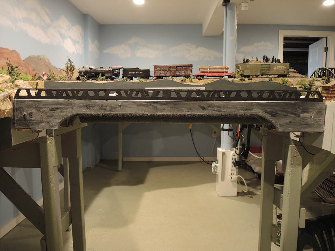
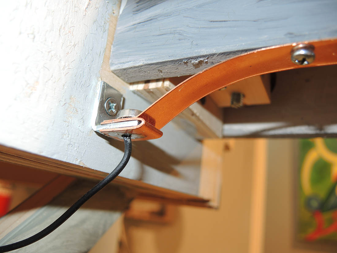
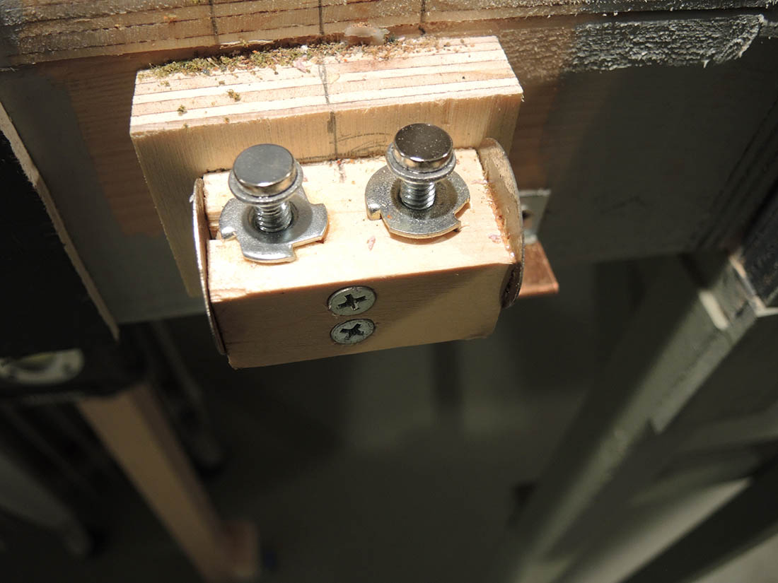
The first photo is the bridge shown on my layout that is the subject.
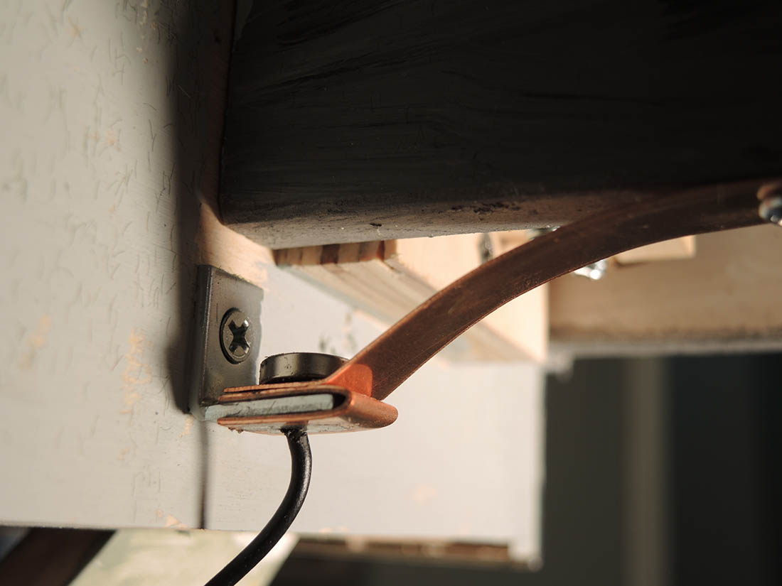
The second photo shows the mechanical items that make it work.
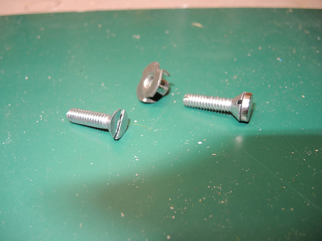
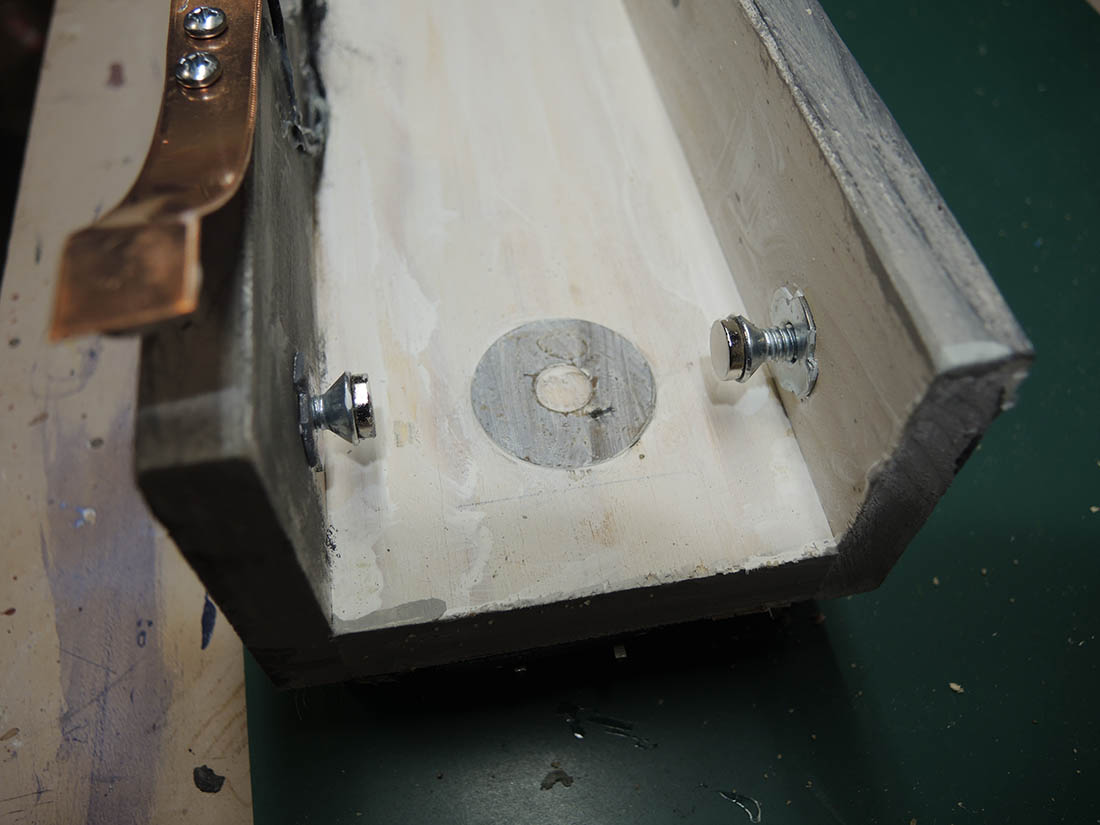
I used 1/4 -20 flat head bolts that I cut a slot in the end for a screwdriver.
Also shown is a 1/4-20 T-nut and one of the bolts shows a 10 mm super magnet which was superglued onto the head. This is typical to all the bolts in the system.
The 2nd photo is #2779. Various photos show the slot cut in the end of the bolts. Before gluing the magnets onto the bolts file the top of the heads so that they are very flat.
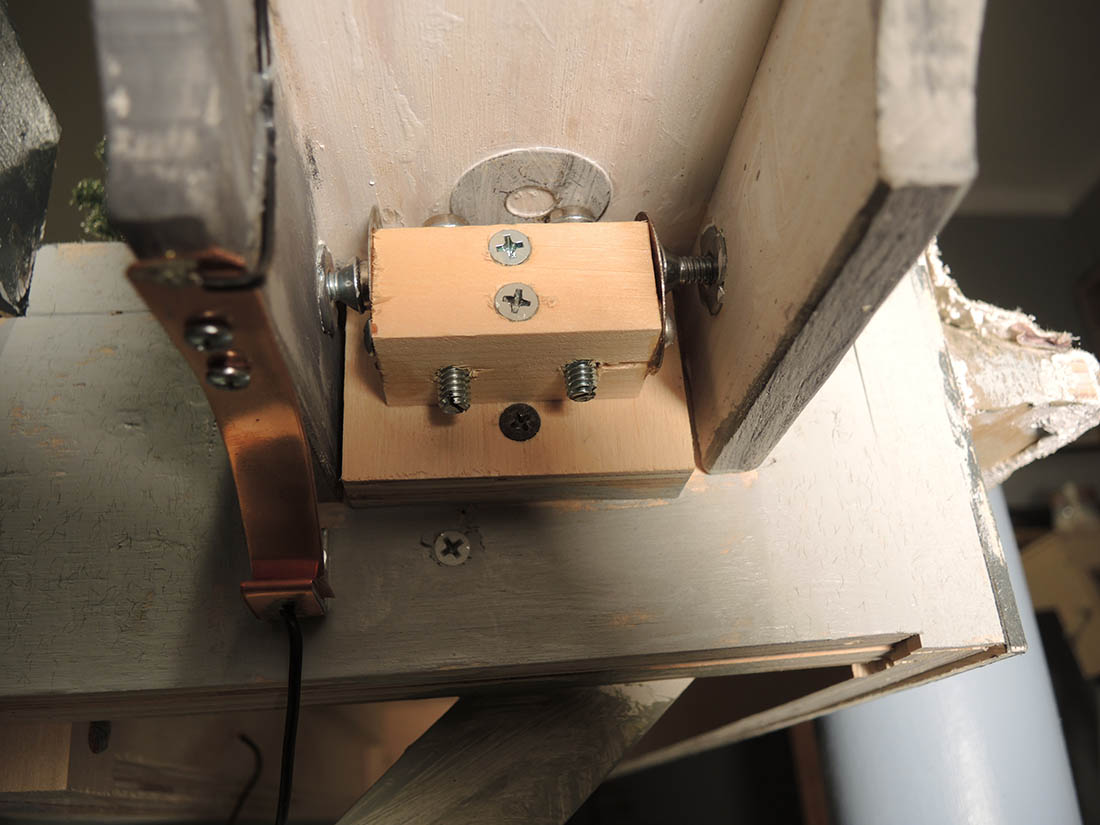
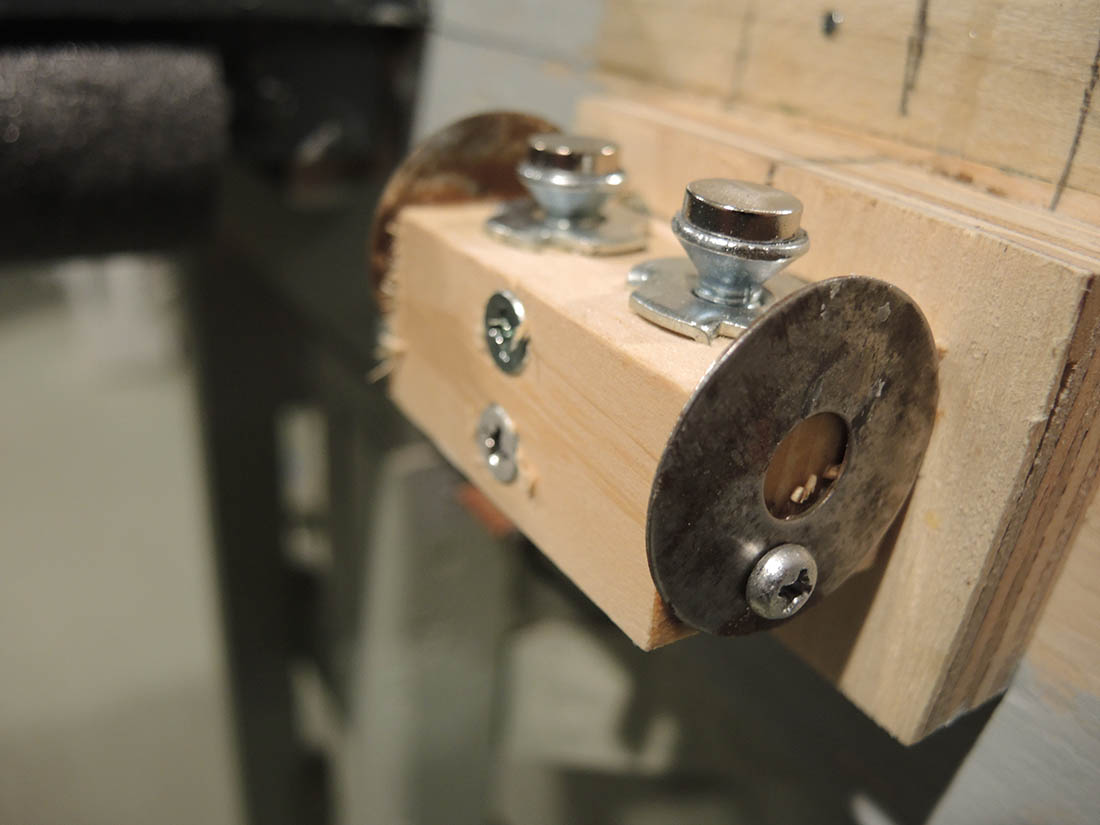
Various photos showing the underside of the bridge and the relationship of the mechanical & electrical components.


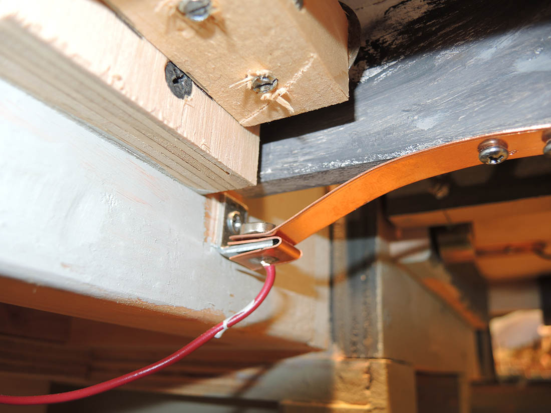
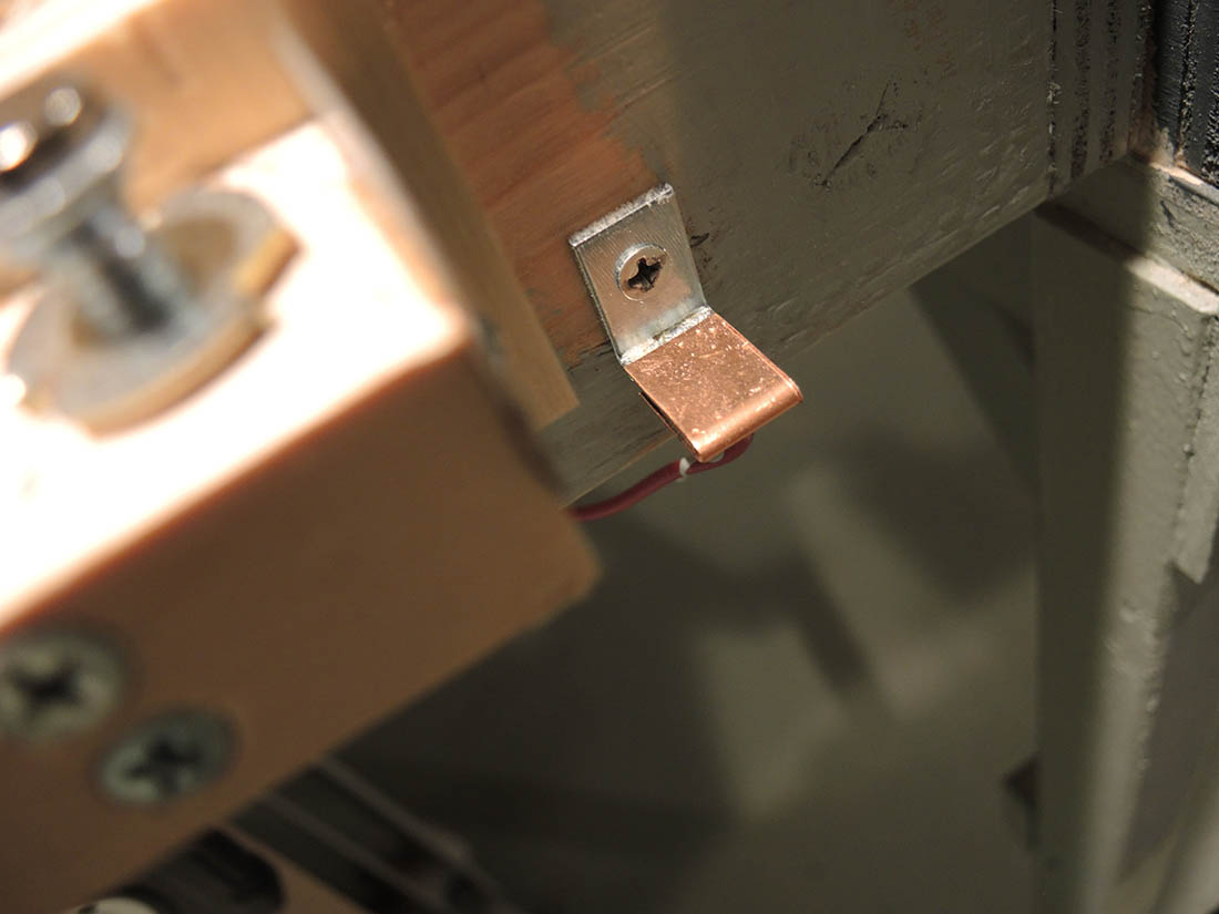
The photos below show the electrical contacts with a 10mm super magnet glued to the flexible copper strip which automatically adjusts to provide a good electrical connection.
This also shows the wires which go to the tracks and to the power source. Obviously you need one for positive and one for negative.
The stationary contact is a steel angle with the copper wrapped around it. This provides the stable contact and also the steel to which the magnet is attracted.
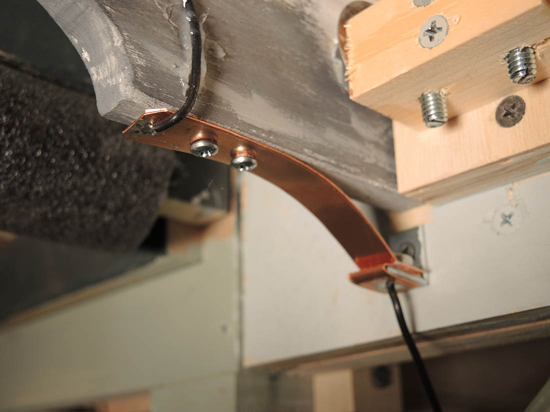
These photos show the underside of the bridge with a thin washer glued to the wood to provide something for the magnet to grab. You can use any steel or iron that you have but it must be flat. This has to be located wherever a magnet must attach.
Also note the structure of the vertical lift mechanism. I chose to use 2 screws so that I could a adjust tilt if necessary. The lateral adjusting screws are attached to the movable structure, in this case the bridge itself. Use T nuts for the internal threads where needed. I also glued the T nuts in place.
These photos show the stationary contact which is a steel angle with the copper contact bent around and glued to it.
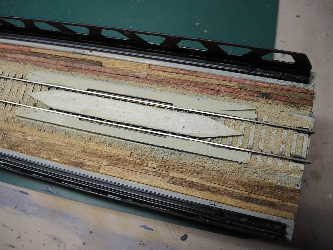
Also shown is the Atlas rerailer track used to assure that the train wheels align properly. These rerailers are used at both the entry and exit from the bridge and also on the stable layout entry and exit points.
If you decide to use this method on your layout you should design it so that the adjustment points, both laterally and vertically allow both positive and negative adjustments. What I mean by this is that the adjustment screw placement should allow the track to go beyond the ideal position both vertically and horizontally.
Also I used the magnets instead of just bare screws to provide control of the positions by keeping everything pulled together.
A big thanks to Paul for taking the time to send in his model train lift bridge. Clever stuff.
Now on to Gary who has come up with an interesting effect:
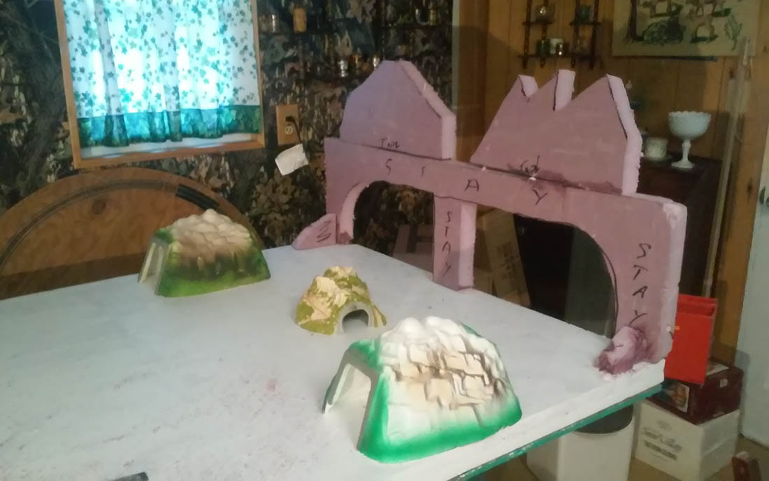
“Tunnels made from roofing foam and pillow stuffing.
Gary”


That’s all for today folks.
Please do keep ’em coming.
And if today is the day you get going on your layout, the Beginner’s Guide is here.
Best
Al
PS More HO scale train layouts here if that’s your thing.
Need buildings for your layout? Have a look at the Silly Discount bundle.

Paul’s removable bridge shows some important details. Having fine adjustment, and making it easy to carry out are so important. I like the electrical contacts with their magnetic enhancement! That seems to be a really good idea.
Paul my grand daughter loves your frozen mountain. She asks where’s Elsa and Anna ?
The Critic
Very clever but complex solution
Why not just use a simple plug for the power supply?
The multi axis adjustment is well done
I love reading the pieces and viewing all photos.
My eyes glaze over at all the intricate work.
True artistry.
And electrical engineering.
Paul…..great job with the bridge…….wish I had your skills……..best was the contacts with the magnet……what an idea.
Robert the credit you gave belongs to Gary for his mountain. Roger I enjoy working out solutions to problems. Sure a plug would work, but what enjoyment do you get out of it?
Kool set up.!!!!
Gary : my grand daughter loves your frozen mountain. She asks where’s Elsa and Anna
Nice. Great design with great results.
Jim AZ
Al, Thanks again for what you do. The following tip is for builders who want
some machine tools in their shop. Surplus machine tools are fairly cheap. The
problem is that they always have three phase motors. Not to worry. You can get
three phase from single phase with two AC motors , an A groove belt and a couple
of disconnects. With 200 amp 240 volt service, you can pull up to 50 horsepower
at 240 volts three phase. That enough to run a lathe, milling mach. , drill press
and shop dust control blowers. No machine will bog down with 50 horses
behind it. A more detailed account is available, if wanted….RJL
Why not cut an Atlas retailer in half and place half at each end of the lift out bridge?
Both presentations are of interest. The bridge is something like myself would think up, nobody believes the Power Factor Correction panel I thought up this past Winter. Not the dime a dozen as Amazon sells.
The mountains look gloomy, haunting and nightmarish. It’s all good, just imagine a mansion in there someplace.
Rich
FORGOT… the 3 phase info RJLJ is talking about is spot on. A phantom phase is created, don’t run control circuits with it though, will not stand up. And then ran across same difference with 3 phase 35KV stepdown xformers. Yup, same mock phase picked up through windings with blown fuse. Work just fine except where control voltages required. IE- switch to generator circuits lmao.
R-again
Impressive. I considered doing the same thing for my 6×12 N Scale Duck under but stayed with the duck under part. I.E. lowering my office chair to scoot under the 46 inch high layout. But again, impressive and no small amount of hard work and detail!
nice. good tips.thanks.
nicely done