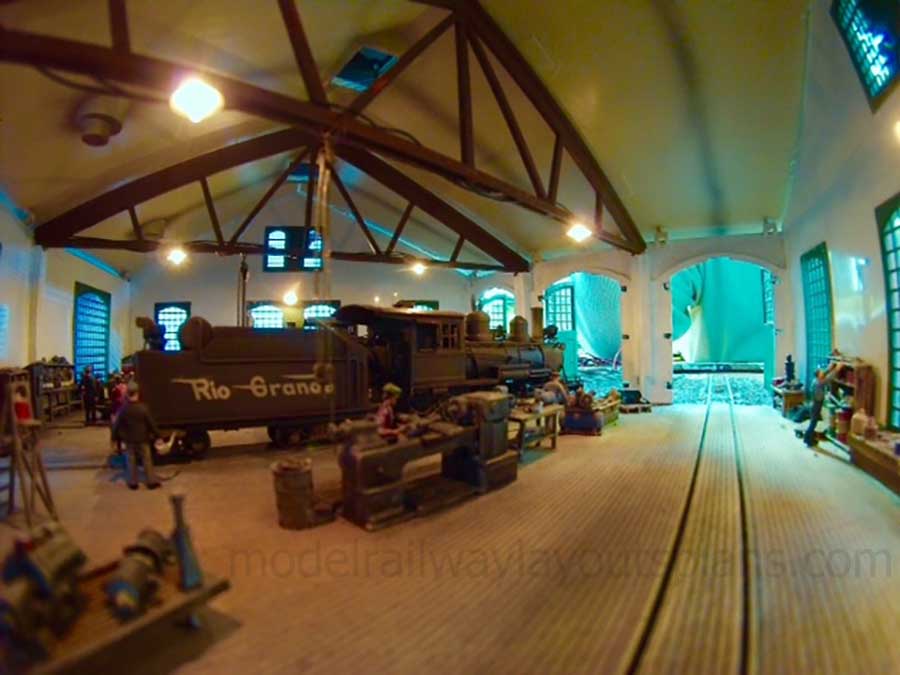
Brian’s been back in touch with some more HO scale roundhouse interior details:
“Hi Alastair, fantastic response to the write up. I did reply to the questions asked in it.
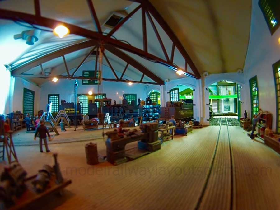
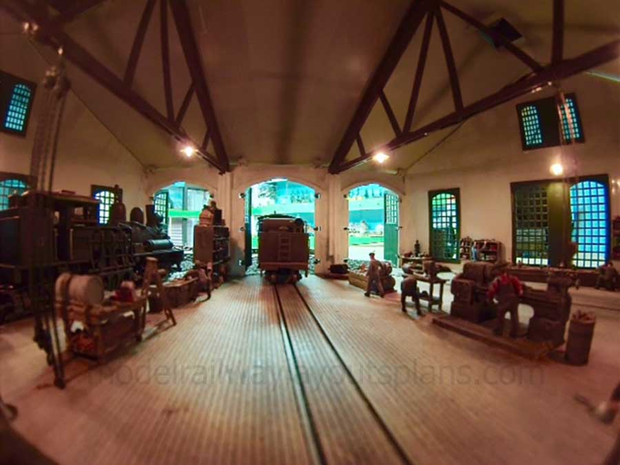
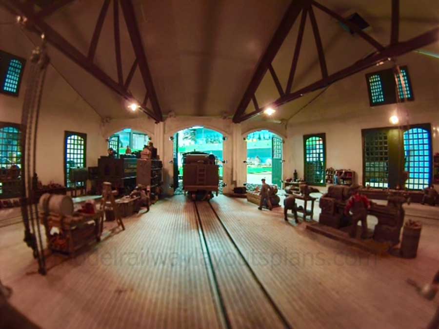
I have a few more photos taken from the inside of the building in case you would like to publish these as well.
The question about the locomotive in one of the photographs, it is the front of a 3 truck Shay – a logging locomotive.
The photos below were taken with a GoPro Hero 3 camera which has a nice wide angle lens to get some nice shots of the interior. I connect this camera to the GoPro app on my cellphone, lift the roof off the building, place the camera inside and then put the roof back on.
The interior lights are turned up to 12 volts to brighten up the interior for the photographs, but during normal operation, they run at 6 volts for the correct lighting effect. This is a reply to someone who said that the lighting was a bit bright. No offense taken on the comment.
All the best
Brian”
(If you missed Brian’s last pics, they are here.)
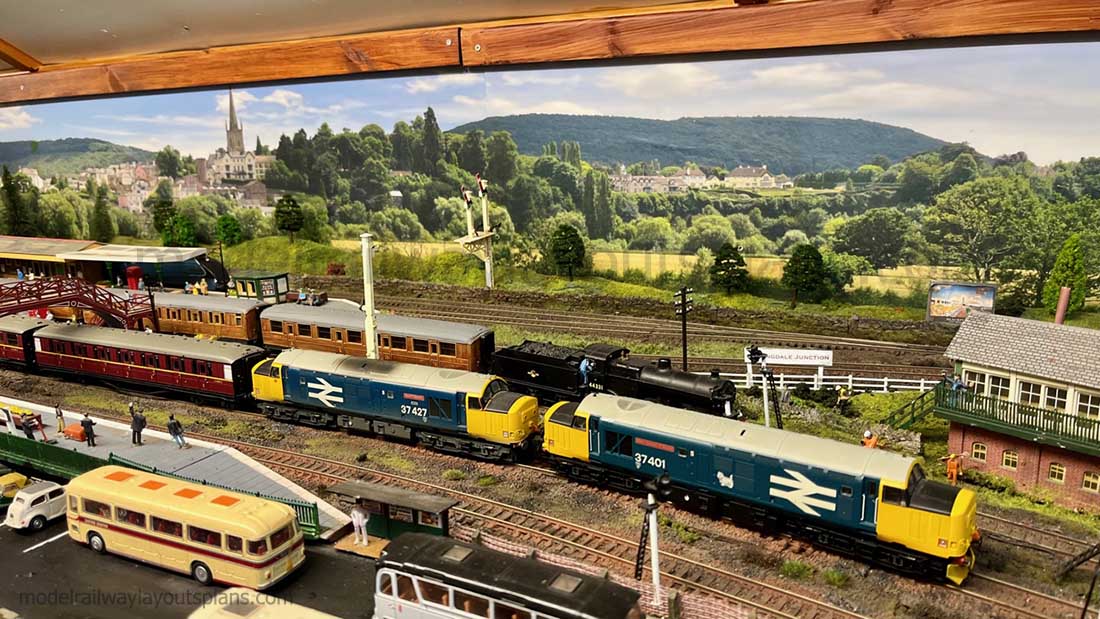
Now on to the very latest from Dave:
“Hi Al,
just uploaded this video showing the Power using Double headers, or as they say in America ..in Consist… well it is a wet cold day, so what better than running a few Trains.
Regards
Dave”
Now on to Lester who touches on something that always comes up on the blog – train speeds.
I know some of you like to run your trains rather fast – and all I can say, your layout, your rules.
“Hi AL.
I read your email every time I get one. I enjoy them so very much.
I’m not exactly a newbie as I have made at least 10 layouts since I bought my first train set as an adult in December 1963 for my two sons, then ages 3 & 4.
I have made or helped make layouts in O gauge, HO gauge and N gauge and have had fun with all of them.
I’m current in HO gauge and probably remain there for the rest of my life.
I don’t know what category in which to put this, but I’m a number cruncher in real life (accountant) and here are formulas for calculating speed of HO/OO gauge trains.
actual feet/time in seconds * 59.386 will give scale mph
actual meters/time in seconds *313.493 will give kph
O
MPH: actual feet/time in seconds*32.728
KPH: actual meters/time in seconds*109.091
N
MPH: Actual feet/time in seconds*109.091
KPH: Actual meters/time in seconds*575.88
Lester in Georgia, USA”
Next, on to Simon:
“Hi Al
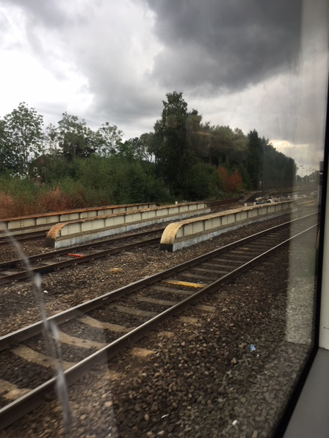
Love the posts. Thought I’d pose a question for you and the readers.
Can anyone name these lineside structures and what purpose they serve? Many thanks
Simon”
A big thanks to Brian for sharing his stunning HO scale roundhouse interior details.
And can anyone help Simon? I have to confess, I’m as keen as he is to know. What on earth are they for?
That’s all for today folks.
Please do keep ’em coming.
And if today is the day you get started on your layout, the Beginner’s Guide is here.
Best
Al
PS Latest ebay cheat sheet is here.
PPS More HO scale train layouts here if that’s your thing.


Hi Simon,
I always thought they were ‘joists’ for a small bridge. They way I understand it is that there was not enough room beneath the bridge to put substantial joists in so the construction method was to make some of the joists above ground. They are fabricated as ‘box section’ rather than solid beams.
As always, I could be wrong. It’s not something that was explained when I learned to drive trains.
Best wishes.
Hi,
The linrside structures are the main spans of a girder bridge carrying the railway over (usually) a road or canal where there is insufficient clearance for the traffic below for any other type of construction.
Hope this helps,
Ant.
Hi
They are definitely structural and as suggested are part of a bridge structure where the beam depth available below the bridge is insufficient for the span required.
In structures like this the issue is beneath the span. Insufficient clearance means that the load bearing of the span is raised above the load, as for example the Forth Road Bridge.
Very nice pictures
Yep, plate girders for un underbridge.
Lovely pictures inside the enginehouse, but I don’t believe any floor exposed to steam locos and heavy engineering would stay THAT clean! Well done.
Rod
Simon,
They sure do look like Plate Girders for a bridge as mentioned, BUT what I’m NOT seeing, in behind them (in the background) is the lowering of the landscape to beneath the bridge (how we as modelers make scenery) BUT that said, I’m not sure either the picture could be deceiving too…. ~Hemi
Awesome photos! Really great. I, also, agree with Rod on the exceptionally clean floors but don’t want to take anything anyway from such a wonderful job of detailing inside a structure. Brightness and camera info explained quite well. EXCELLENT!
Lester, I’m confused by your formulas. Am I to assume the . represents a / in the directions below, meaning that an N gauge train will travel 109 feet in 91 seconds?
N gauge – MPH: Actual feet/time in seconds*109.091
If that’s not correct, would you explain it more clearly?
In rare cases the plate girder bridges were used where it’s not possible to get a solid roadbed, essentially building a bridge on the ground. Maybe a swampy area, or a peat bog. Unusual to happen these days with modern geo-fabric and cement like chemicals which can be mixed into soil to make it more stable, but in the past it was done when necessary.
John USA
I worked in my fathers shop for many years. Every night the floor had to be exceptionally clean despite the fabrication and manufacturing events that took place all day. This was very reminiscent of my early years with my father.
Simon what do you think they are?. Have you checked all around to see what they might be there for?. Like a stream or road underneath. Check it out first.
My understanding of Lester’s formula is that the “dot” is a decimal point and the N gauge formula for MPH can be simplified to “Feet divided by seconds then multiplied by 109”.
Lester is an accountant and is therefore obsessed with the need for accuracy in numbers. he has provided us with some very useful information. However, In all of his formulas the multiplying number can be reduced to the nearest whole number.
As modeller railroader we usually only need to know that the speed of our trains is in the correct ball park range so in this example, rounding the multiplying number down to 100 will almost certainly be accurate enough for our needs.
Model railroading is supposed to be fun so don’t get bogged down unnecessarily.
Trevor LL.
That inside shot is so cool
Brian AWESOME….Lester confusing….Bridges over opening under…I’m thinking you are on a commuter train?…Have a good day all….Mike
The amazing thing about the roundhouse photo’s is…they look real to me! I had to zoom in to take it all in.
An example for N gauge. If a train travels 16 feet in 26 seconds it will be going 67 MPH.
16/26*101.091
If you enlarge the photo, there appears to be another bridge and modern road lighting to the right. These could be an old underpass that was filled in when the new road was built. To the north of Portland, OR there use to be swampy lowlands towards the Columbia River. The railroads crossed it on low trestles for the bridge approaches. When the city filled in the area for industrial sites, the railroad just buried the trestles in ballast and left them in place. Tim
They are built up plate steel Bridge Girders.
the structure is probably a( T ) rail bridge where one rail is placed upright and the next upside down all the way cross the opening and the pieces on top that you are seeing are the top caps for easy identification
Hello Al,
Your articles and comments are very interesting and helpful. And as I plan and develop my second upcoming HO train layout, as my youngest Grandson grows up (he’s still young to really ‘get into’ this great Hobby) ; and with all the fun times this Hobby is going to bring our famiy.
I have several stages drawn out and I’m also developing a “working budget” so as to control expenses, from adding additional circuit breakers, lighting for maximum coverage for the layout and work bench and my text desk. All for maximum fun! I’m certain there are other factors. However, I foresee challenges in the Electrical Wiring, in all aspects. The construction of the layout ‘table’s will be great, because I’ll be constructing with added ‘weep holes’ so as to string wires and camoflauge train switches and other electrical ‘runs in concealment over and under the table.’ top.
As of recent, I’ve been studying your concepts/ideas regarding the building of water i.e. Water falls, streams and rivers and ponds. I intend to design/build several water features, also.
I’m looking forward to many more of your very cool ideas and helpful advice.
Regards,
Ralph O.
A Proud American Viet Nam Veteran.
Those Lineside girders are probably taking the carrying the stresses of the track & train weights over weak ground e.g. subterranean culvert, natural drainage route. Seen also around stations sometimes where there is a pedestrian subway connecting platforms.
Dave and Brian are very talented modelers with extra skills in photography. As dedicated modelers they are rare in having the necessary extroversion and use their abilities to SHARE their talents. Your critic is just jealous Al. Ignore the comments and share modeler comments on.
Whilst there will be modellers who want to recreate an accurate version in scale of what would have been or is in real life there will be some, and I suspect I would be in this group, that would like to create what we wish could have been or be as an escape from what is there now.
All are valid I believe
Many thanks Lester for these numbers -have often thought about locomotive speed – so will now retain this information.
Sure, agree with other answers. Looks like a pony/plate girder bridge with common center span for double trackage. And have seen them filled in with ballast as such, used in cases of not needed long spans. Must of had road or rerouted stream once upon a time underneath.
Round house- Cannot tell if live or memorex, meaning it sure appears real. Now DAVE, thought he was part of daily news. Have never seen RR any better and always changing strategies. Now I like the tunnels, rivers, bridges but the around the room concept with his documentation is top notch. Only thing the big arch-span bridge looks more like it should be crossing a gorge or maybe attic stairs? Don’t change a thing though.
The stone arch bridge in Mechanic Falls, ME is my favorite. Blue Crane hangout underneath, crosses between private properties these times (abandoned). Best yet is the underwater railway in Princeton, ME. Stands right out on Google Maps. When water level lowered it’s a mystery roadway across St. Croix flowage in the middle of nothing.
Regards, Rich
Thank you as ever Al for running this blog; Brian and Dave and all your contributors always have something interesting and ideas think about and all show extraordinary talent – for someone who has their trains and track in boxes in the loft at present, its inspiring to see what other folk are doing – please keep it coming!
Great pics Brian. Could you give a tutorial on how you take such great pictures? The perspective are so real! When I take pictures the always look like pictures of a train layout.
Al: There is one in every bunch, ignore him! I find your selections wonderful, inspiring and a marvelous window into a lot of very creative model railroaders world wide. You do great work by giving us so many opportunities to share and admire.
Brian gives us a level of detail we all wish we could do, he is a great contributor. He makes me think how to take my layout to another level.
Dangerous Dave is in a class by himself! A generous man who shares his passion with us and gives us so many videos , each one of which is an inspiration. I’m in N gauge, however, Dave’s how to instructions have provided me with many an idea and just plain enjoyment watching and listening.
Change nothing!
BTW, We need a UK based world-wide model RR meet and greet. Preferably on a steam train!
Keep them coming.
John , LINY
I was going to make a comment, but I think it all been said. FANTASTIC ROUNDHOUSE. Sorry a comment.
Hello Al,
I’ve enjoyed your website for several years now and was pleasantly surprised to read the wonderful post from Dan about a brick from the old D&H roundhouse that he gave to his father, lost and then found again years later on eBay.
I too lived near and worked in Oneonta for many years and know both the area and the D&H very well. I actually lived in the former home of Jim Konstanty (the owner of the Sporting Goods store where young Dan had the plaque engraved) in Worcester, NY during that time. It truly IS a small world.
All the best,
Matt
@ Appookta
To clarify:
/ = divide
* = multiply
So divide the number of feet your train travels by the seconds it takes to travel that far and multiply the answer by 109.091 (for N scale)
What’s not to Love, FANTASTIC
Al;
Please keep doing what you are doing, and how your doing it. Forget about the complainers who just have to do negative posts or thoughts. I wish like a lot of people that I could model or have a layout as detailed and complete as Dave and Robs. They have helped us all in some way.
Bud in Mission Viejo, CA
Great photos Brian and Dave. Thanks for the time you take in sending these photos. I appreciate it very much as I am new to this hobby and a 71 year old Rookie.
Feel free to ignore your critic as they have forgotten one salient point. You can only post what people send you. If you make daily posts, that means people need to send you stuff pretty much daily. If that happens to be only Brian and Dave, so be it.
You should take great delight in your post(s). You provide a valuable service to many andI for one appreciate it. This blog keeps me interested when I have health issues that keep me from doing much an my framework-only layout.
Thanks
Sad that one soldier in the troop who marches out of step attracts more attention than the rest who are marching properly. Please do not be discouraged by someone who fails to appreciate the inspiration that Brian and Dave give. Of course, there are other fine contributors, but a Hall of Fame has an expectation that its members will feature prominently – what a travesty if a HoF member were to be hidden away. Today’s offering is the perfect antidote to gloomy November weather – thankyou.
That is amazing detail for HO Scale.
I would have bet that it was O gauge or larger!
Fantastic work.
Al, I guess your line of work invites the odd looney to jump in with a mouth full of ignorance. I remember the “Ad man” who sent a real nasty-gram bad-mouthing everything you did and how you did it. Guess he was hurting for accounts.
I had just opened this email and was looking at Brian’s first photo as my wife walked by. I got her attention and just pointed at the photo asking, “what is it?” She said something about trains. I replied that it was an HO model of a round house. She said it looks real. Indeed!
Great site you run, Al. And my trains, from my first Marx all metal (1940-ish) to the Lionels (1952 -) and the HO bits are also in boxes. But this site fills in a void shaped like a N & W J-Class 611. Thank you!
Great train running again by Dangerous Dave. A little info about “double heading” or “consists” in America.
The Americans will sometimes run three (3) diesel loco’s at the head of the freight train (consist), one loco in the middle as a ‘helper” and another at the rear end of the “consist” as a pusher.
With all these loco’s positioned in one long freight consist, and working together, they call this M/U’s or “Multiple Units.
One “slang” term used by many of the model train manufacturers is called a “lash-up” but true engineers (train drivers) despise this term. It is officially a M/U.
Peter…..Buco Australia.
Hello Al,
I agree with all of the comments provided.
You give all of us a wonderful lift when we read your blog.
Please do keep it up and thank you to Brian, Dave and all of your contributors.
Truly inspirational, entertaining and enjoyable.
I am working on some additional projects that I hope to send in soon.
All the best to you sir.
Allen in Indiana, USA
Re negative comments! When working, voluntarily I might add, for the N gauge Journal, I submitted several technical articles on various aspects of our hobby. As an electrical engineer I put together an instructional article on lighting, detailed in two parts. Lo and behold, some critic, not an engineer I discovered, decided to pull it apart. I was really offended and quite angry about it. I wanted to respond in the next issue but the editor suggested ignoring it. It really got to me at the time!
All I can say to the those people that think their better than the rest of us is “if you’ve got nothing good or constructive to say, don’t say it!”
And thanks to you Al for the many hours you must spend daily on putting this fantastic blog together for all of us. We have a wonderful hobby and its great to be able to share our efforts wherever we are and what level we’re at.
To Brian and Dave and all of the Hall of Fame – keep doing what your doing!
Thanks again Al.
Best to all
Brian, Wokingham UK
Brian you have done a great job for the interior of the Roundhouse comes out showing all the detail and ith the lights its excellent , and Simon those re usualy supports for a bridge eith road or river running underneath , they hve them on the NYMRailway , and have a 2nd use for them , they clean the carriages parked up in between, stood on top of them with a long brush in hand ..
Thank you all for your kind comments re Brian and Myself , i shall no doubt continue to send in videos of my layout with any tips I can offer and any alterations that i make , must admit its getting harder to think of improvements , and as for a new layout , just getting a bit old in the tooth as they say to contemplate doing it again …Thank you Al and all the members for your support ..Dangerous Dave
Reply to Dave (DD), I second what you have said in your last comment and thank you for it. We both continue to send in contributions, firstly to show what we are capable of doing and secondly to help (if we can) other modellers to show what can be done in this fantastic hobby.
I am sure that both Dave and myself choose to ignore all the negative comments made by some people on this blog. I do like constructive criticism when needed, it always helps to improve my modelling skills.
Dave (DD) I always watch your videos and find them exciting, especially to see what you are up to next.
We all admire what Al does for this hobby and appreciate the work that he does to keep this site going – please keep it up Alastair, we all appreciate what you do.
Brian – the HOn3 guy in Knysna RSA 🇿🇦
So realistic!!!
Looks like a great RR to work for.
Heep up the modeling
Al, you are doing a great job presenting great modeling and fantastic tips. I do have one comment about what terminology people use. People say “HO gauge” or “N gauge” and I want to ask them, “Gauge? Does that mean you are modeling in standard gauge (4′ 8.5” between rails?), narrow gauge (2′, 3′, 3m between rails?), or broad gauge (5′ or more between rails?). Of course I don’t ask the question, but one of these days I won’t be able to restrain myself. What they mean is “scale” of course. O scale is 1:48, S scale is 1:64, HO scale is 1:87, N scale is 1:160, and Z scale is 1:220. There are many variations. I once counted some 60 scales in use around the modeling world and most of them had several “gauges” available to the modeler. So, please be a little more conscious about your terminology.