John’s been in touch with how to build a model railroad control panel:
“Al,
This article is the next following after my “how to build your own under layout switch machines”, and is about the construction of the layout control panel.
First, I got more 6mm or ¼” Lexan® plastic sheet to use as the board. I chose this because it can easily be drilled, sawn, and won’t contribute to short circuits like anything aluminum would.
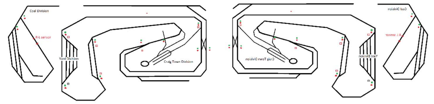
I laid out my track plan in schematic form, and tried to follow the “protocols” of the real railroad interlocking plant boards I have seen and worked on.
You may remember, I was a signal maintainer on a USA East Coast railroad, now part of CSX. Schematic picture below left, then had to figure how to print it in reverse, below right.
(All images are clickable.)
I next got my plastic and some drafting chart tape and laid out the reverse schematic on the bare clear sheet, it’s white below because I put paper under it so I could see the tape!
The yards, sidings and storage tracks are ½ size of the mainlines. I worked out the hole size for the Light Emitting Diodes (LED’s) on a scrap sheet of plastic.
To make sure all the LED’s and switches were uniformly spaced, I made a template for marking the hole spacing.
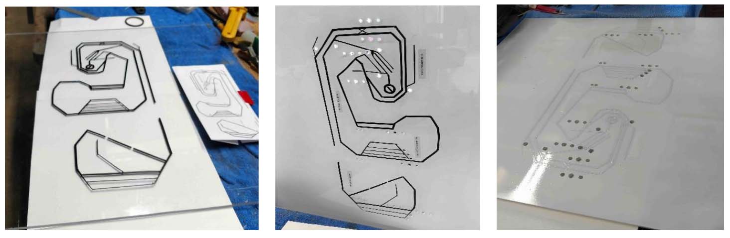
Once everything was marked, I drilled the clear plastic with the tape reversed schematic applied. I then spray painted the back side of the panel white.
A note or 2 on the wiring. Remember, the lamps are LED’s – So they will only light up when the polarity is correct, they ignore reversed polarity because of the “D” or the diode in their name.
Also note that my switch machines run on 5v DC, and reverse when the polarity is reversed. 5 volts is too high for LED’s which take 2.5 to 3 depending on the color.
I soldered a resistor to the cathode side of the LED’s (the slightly longer lead) so I could keep track of where to connect the + and – sides of the LED.
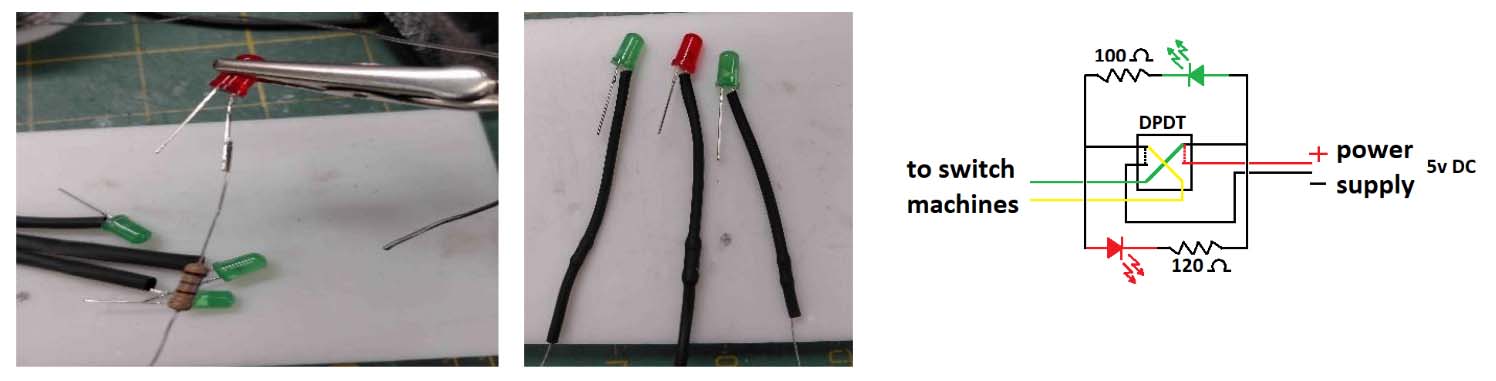
The schematic shows the DPDT switch connecting the power to the upper contacts, so in this case the green LED is lit.
I also put heat shrink tubing over the resistor to reduce the chance of a short circuit behind the control panel.
Note the wires to the switch machines are “hot” all the time, and their polarity changes when the switch is moved to the other position. This will allow me to connect LED signals to the switch machine wires at the location for their power.
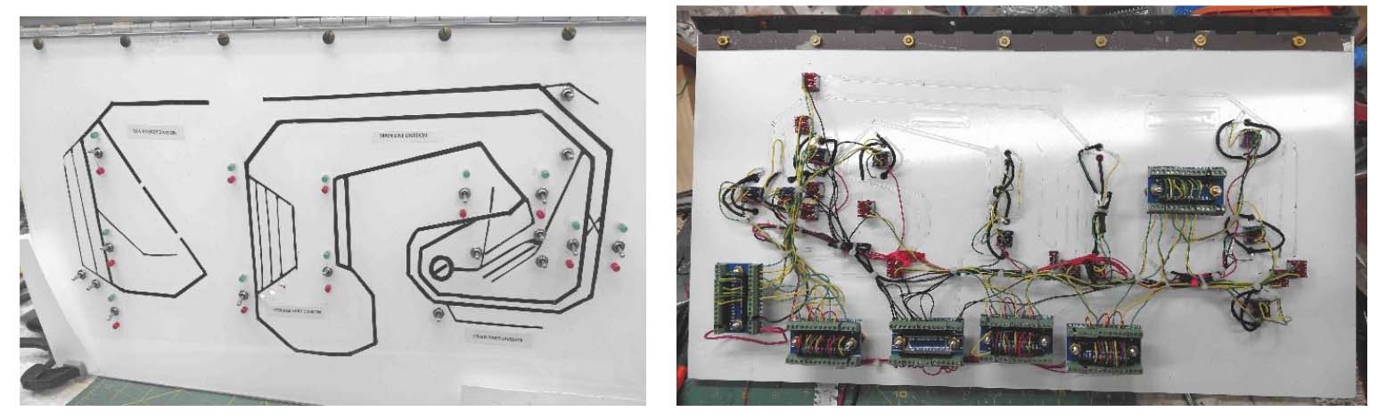
The wired and tested panel is above. The bigger blocks on the back side are terminal blocks to attach wiring from the actual layout.
Green lights will mean the turnout (track switch, or for you UK folks points) are lined for straight through, the divergent route is red. This is consistent with actual switch stand flags and lights on real railroads.
Below is the panel ready to mount to my layout board, and for wiring into the devices on it.

The green LED’s look almost white in the photo but are indeed green.
Also note that not all of the control switches have LED’s, those without are momentary – center-off switches to control Atlas® type switch machines.
I may add a relay and a LED to indicate when these “un-signaled” tracks are lined for trains to come in or go out, but that will be much later.
Next step is to mount the panel and begin wiring the layout. I’ll also start the third side of the layout, mountains and mines above storage for trains and cars underneath.
I’ve decided to wire everything plain DC until I can scrape up the $$$ for DCC, once I have the Rail-Pro system in hand, the change-over should be pretty simple.
John”
“I enjoy your posts very much.
Many good ideas. Here’s one I’m trying.
I have a small bedroom for my new layout. I am combining HO and N to try and and get some degree of depth. The steamer in the front is HO and the coal train is N. Some will say ‘not prototipical’, but I’m having a ball.
Andy.”
“Greetings from Los Angeles Al!
The commercial plants and trees can prove to be costly if you need several…
I made these planters on ether side of the door by wrapping pipe cleaners around a sharpened pencil and then pressing them into the desired shape. Then I paint then with inexpensive acrylic green and glue them into the planters .
The planters are BEADS from the craft store..then I glue them to my structures ,or where needed om my layout You can make dozens of these for next to nothing…
John”
A huge thank John for showing us how to build a model railroad control panel – clever stuff indeed!
Thanks to the other John and Andy too.
That’s all for today folks.
Please do keep ’em coming.
And if today is the day you poke boredom in the eye and start laying track, the Beginner’s Guide is here.
Best
Al
PS Latest ebay cheat sheet is here.
PPS More HO scale train layouts here if that’s your thing.


That’s over my head!
I bought 12 volt LEDs because all accessories on my layout, including the Tortoise switch motors, run on 12 volts. I use one of the SPDT switches in the Tortoise to operate the LEDs. I use CAT-5 cable for all Tortoise connections as it has 8 conductors and the Tortoise has 8 terminals. Nice and neat!
(I use the other SPDT switch to power the frog.)
I am building my own layout control panel and the wiring of it is a learning experience for me. From what I have read so far, and for my first trial wiring of LEDs, I wired the resister on the short lead (the cathode) from the LED, as I have read online, and everything worked as planned.
Very nice. How did you do the schematic diagram?
Thanks folks, first, which side of the LED the resistor goes on is moot, BUT be sure its the same side on each one or you’ll get confused polarity wise. I used Microsoft Paint for the schematics, then made them into a PDF where I could re-size and reverse them.
I have a pretty easy to build board that controls a red/green led on a momentary toggle for turnout control. It uses a dpdt momentary toggle one side switches the 5 volt circuit on the led control and the other side changes the atlas style switches which only need a spdt momentary toggle.
Very helpful!! Thanks for putting this together
I would be interested in the board to control LED’s from the momentary toggle.
John USA
Nice job John, and thank you to Al for education on this item. Some of us still have a hard time grasping this of everything I just have read. So in laymand terms on wiring your pixie glass board. One more question, is there a way to wire sensors to the rail that tyes back to the main board, I know there will be more wire and to have a big enough pixie board for all the lights that repersent the rail.
Steve from Saint.Petersburg Florida
Andy, don’t worry about other people and your layout being prototypical or not. It’s your empire and railroad to be run as you see fit. Thank you for sharing, great layout.
Great!
In one of the Old Train Model Books that were available in the 1980’s, there was a plan for a Diode Switching Matrix. I used it and was able to select the end point I wanted the Train to go to and all switches switched at the same time.
With a momentary switch, I only had to select the main line and the destination. My control board of Diodes was 1″ by 2″. Of course, the wires were easily bundled.
Now, I just need to find that book again. The publishing company was in PA;. And that is all I remember.
If anyone knows of that old Brown Book, Please let me know.
Thank you all for your time reading this.
John
Great job on the panel board. To all that are intimidated by electrical work follow a schematic and soon the logic all makes sense. This is great stuff here and can save a lot of money when you have many switches and it really works well.
Andy
Please send in more pics or videos so we can visualize how your layout looks with the 2 scales. I really want to do that but I’m nervous.
John
Great idea on those planters-thanks
Big Al-thanks
I have solenoid surface mounted switches (PECO) to control the frog directions. Can the same system of wiring be good in this case?