Paul’s been in touch again. This time getting his HO scale track transition curve just right.
“Hi Alastair more photos of my progress to date.
Photo 1 is of the three bridges I mentioned in my first email
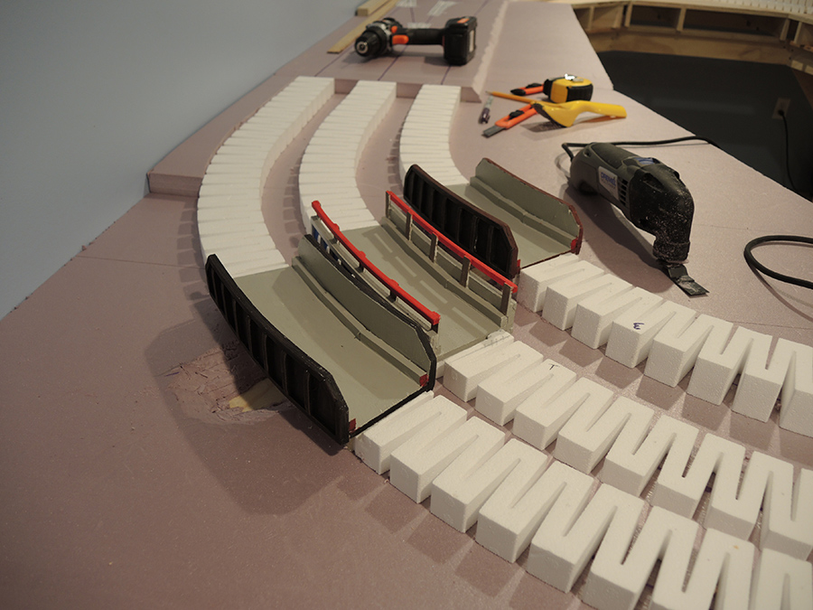
Photo 2 shows the Dremel Multitool I used to carve out the stream into the foam
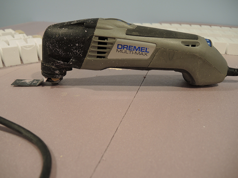
Photo 3 is an overall shot of the layout to date
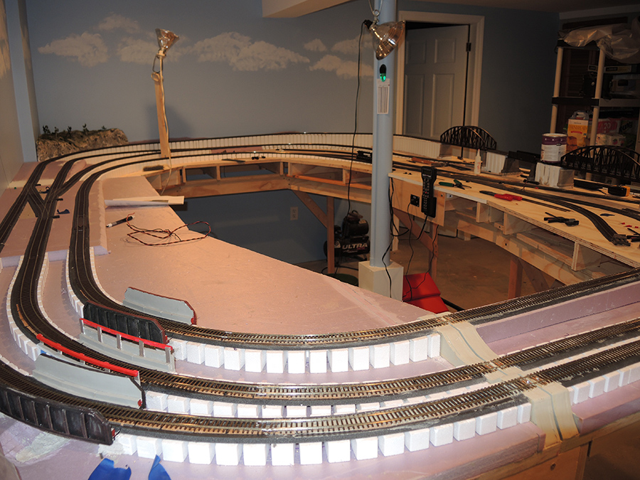
Photo 4 is a closeup of the tracks at the liftout showing the track soldered to the PC ties and gapped
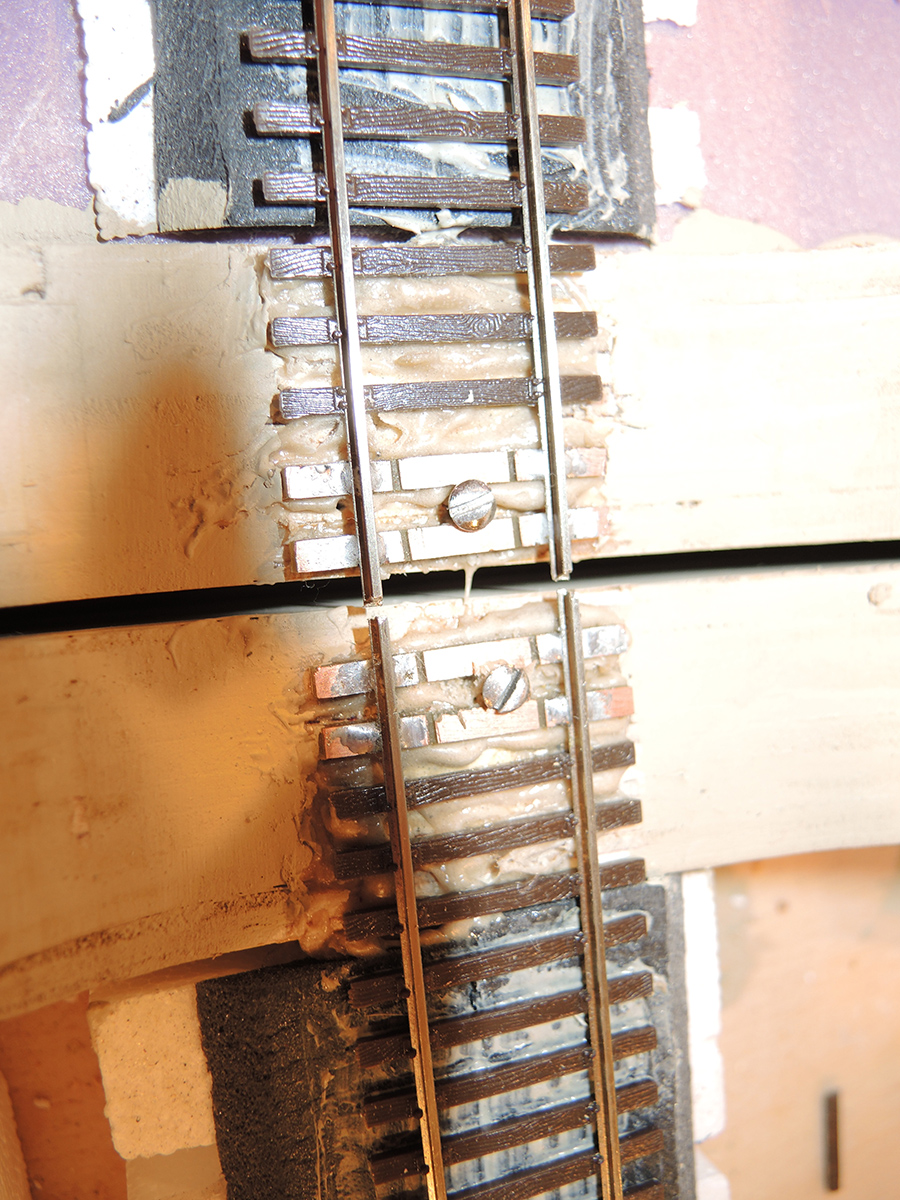
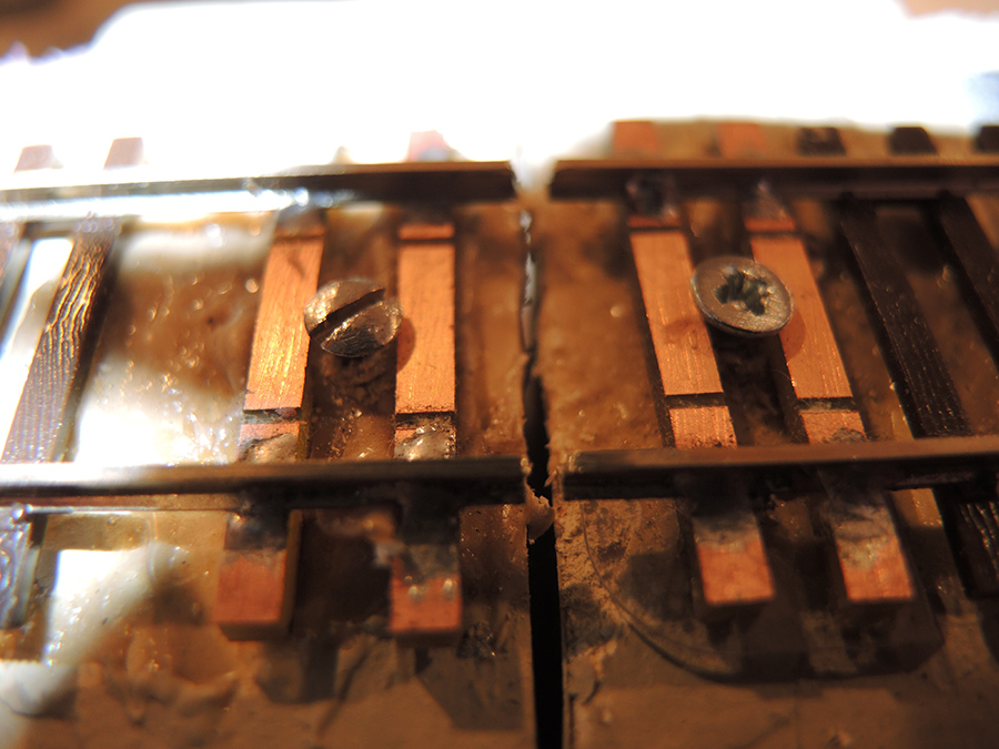
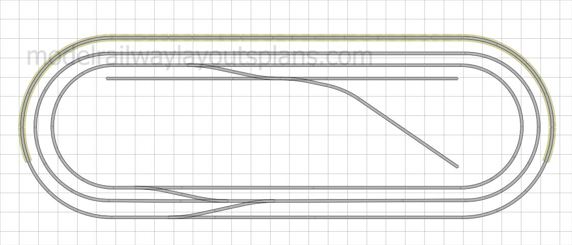
Photo 5 shows the 1mm cork used to provide super elevation on the curves
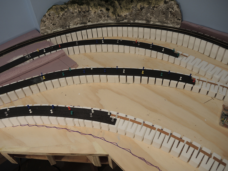
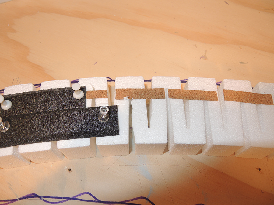
Photo 6 shows what the PC ties look like with the gap cut in them to isolate the tracks from shorting out
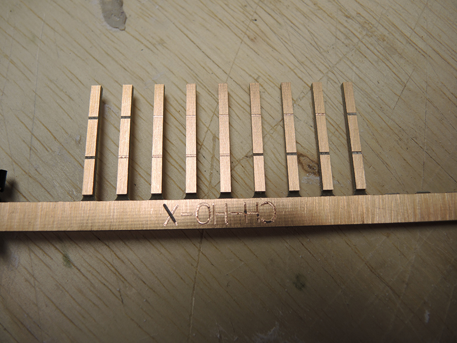
Photo 7 shows the corner hill being landscaped and in place in corner of layout also work platform over tracks
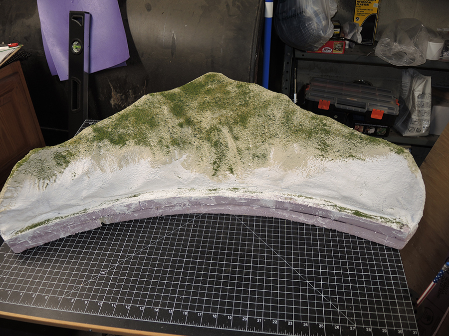
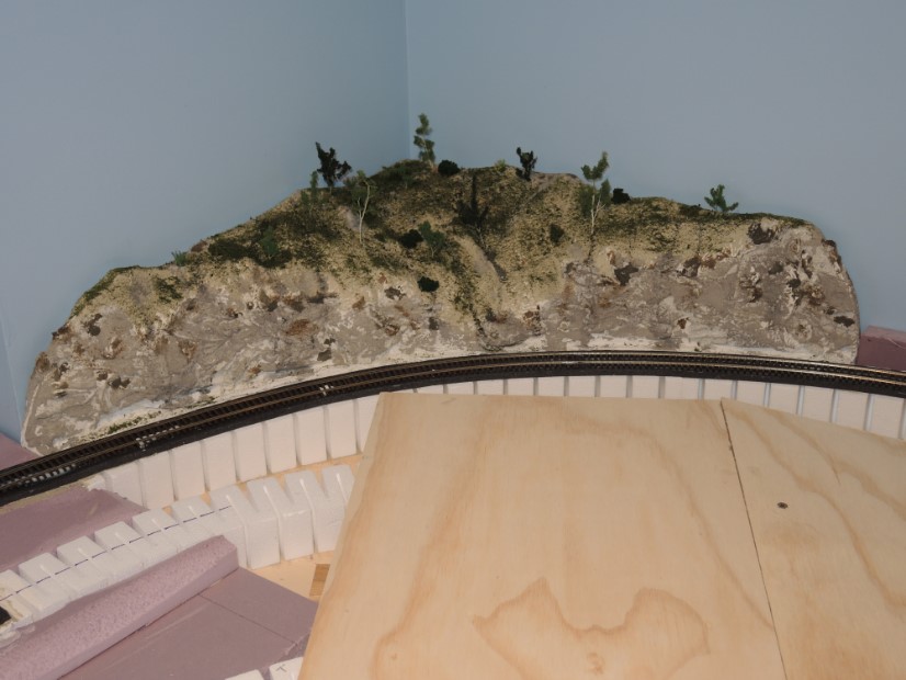
Photo 8 shows the layout drawing which I highlighted with a marker
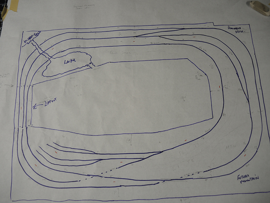
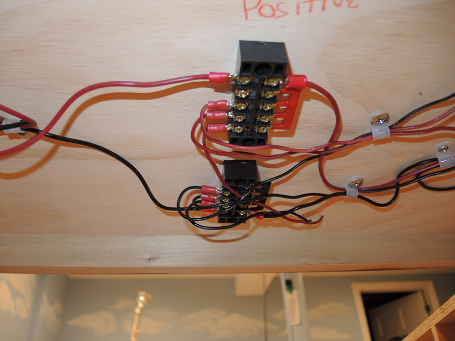
Photo 9 shows the wiring under the liftout –each track has it own connection to the copper contact pads.
Paul”
A huge thanks to Paul – he’s being belt and braces with the track, getting the HO scale track transition curve is spot on.
As you all know, getting the track right is key: your trains have to run snag free before you can enjoy yourself on the scenery, otherwise your layout will be no fun at all – just an endless succession of frustration, blood, sweat and tears.
Paul’s third pic really does show how big his project is. I can’t wait to see it unfold too.
That’s all for today folks.
Please do keep ’em coming.
And if today is the day you get started on your layout, the Beginner’s Guide is here.
Best
Al
PS More HO scale train layouts here if that’s your thing.
Need buildings for your layout? Have a look at the Silly Discount bundle.

Just a hint on the soldered sleepers at the end.
Put 2 fixing screws on the outside, left and right of the track instead of in the middle.
It will save you worries with the underside of rolling stock potentially touching the heads of the screws. Talking of experience.
Very good work Bill. Lightweight and functional. So perfect.
Malcolm
North Wales
Thanks to both of you.
Paul – good clear pics, very useful.
Bill – useful video and some nice woodwork (mine tends to be a tad less neat). One thought – once you have all the track and scenery on that large board, you will need to be very careful when you come to put it onto the legs!
Good work!
Regards
Steve
Lincs, UK
Paul You did what I did no one makes a curved iron girder bridge so you made them. I did the same 18 radius going over a town road .
The benchwork looks great…my question would be: when the layout it complete with scenery, buildings, trains etc., how is it stored? I.E if it’s propped up against a wall out of the way, what keeps the accessories from falling off?
Very, very nice benchwork, Bill. It’s good to see planning from the very beginning. I wonder if there are snap-lock connectors available to eliminate the need for loose wingnuts when assembling or disassembling? Simply snap in and snap out.?
Paul, you have a wonderful layout. Keep up the good work. I agree with the idea of placing the fixing screws on the outside of the rails to avoid shorts.
Warren, AL, USA
Rare earth magnets placed at the track junction could keep track aligned.
Paul
I like your concepts and layout plan. Coup,e of questions:
What are the white risers? i prsume they are commercially available?
What thickness of plywood do you have under what thickness of foam board? Do you have an issue with noise from running trains?
Many thanks –
It still amazes me why folks will still use flathead screws instead of phillips.
Re: Bill’s video. Great idea for stow away layout!
Please though turn your camera to 16:9 or your phone horizontally next video.
Take a look at Dave’s videos to see how much better the full picture is.
Another suggestion for you: buy a battery operated Dremel type tool. Stops the cords falling across other work you have done and destroying it.
Great job Bill! Going to hang on to this email for future referance. Can’t wait to see the trains running on it.
Thanks for the comments re my layout. First off the base board is 3/4 furniture ply from HD as well as all the the rest of the structure except the legs and some bracing. The foam is 1″ and is there to allow for carving the stream and lake. The inclines are 2% rise from Woodland Scenics. The screws that hold down the PC ties have not been a problem since they are tapered on the bottom and nestle down close to the ties. They are overkill since the PC ties are glued down with urethane glue and are not going anywhere. The issue I have right now is with one switch that my sreamer stalls on. The diesels go right over it. I swapped out the switch for another but have the same problem. The streamer passes over all the the other 7 switches. The frog is insulated and I am now in the process of powering it. Hope it works. BTW all my track and switches are code 83 Micro Engineering brand.
Just a word of caution on super elevation on curves, I have had the experience of rolling stock falling over to the inside of the curve if you happen to have too much elevation of the outside rail and decide to run the trains slower than calculated speeds. Needed to reduce elevation by half to keep that from happening again.
I reworked the differential calculus formula with the slower realistic speeds I wanted to run on the layout
The cork strips I used for SE are 1mm thick which equates to about 3 inches in the real world. In the actual real world SE is usually 6″ or more so I am at about 1/2 of that. Now if I could only solve my stalling Steamer over one switch. Powering the frog didn’t help as it turned out to be a shorting problem that I can’t seem to see. The Steamer stops for a second and the DCC starts up all over again as if I turned it on for the first time. Only on this one switch –works fine on the other 7.
Great idea. Looks good and I hope when done it will work equally as well.
Paul, my guess is that your steamer has wheel problems. They are to big, too fat or too close together.. Check with a track gage for spacing. Possibly put an insulating coat of paint on the inside of the wheels, especially the drivers. Compare the wheels to the diesels wheels which dont have problems. Power the switch through a resistor of about 8 ohms at 5 watts wirewound and it wont kill the dcc even if a short occurs. Consider a decoder that has an extra capacitor to cover the short distance through the switch. Good luck.
On your switch problem: try a resistor powered at 4.75 jiggaWatts and a qX22.7 flux capacitor. Guaranteed to solve your issue. Good luck! Nice looking layout…you’re off to a good start!
Has anyone ever seen a curved girder bridge in real life? An open U section has little torsional stiffness. Most girder bridges are quite short and do not need to be curved.
Your layout knocks me off my feet. I wish I had a layout just like the one that you have. I love both freight and passenger trains, and I personally think that your layout is bound to attract attention from miles around.
This is a very nice beginning to a fabulous layout.
James actually has the correct answer but maybe a bit more of the boost juice 🥹. The work appears well thought out and the wiring is within parameters i ‘spose. Just one thing… not sure on closeup shot of rails with 2 different rusted screws? Yup, sure look old and weathered, realistic.
Much advice this AM, I would further file out with round jewelers file slightly larger diameter holes between the ties. 1” even black Sheetrock screws would actually set really flush then. Closeup photo may be up to par with rest of RR caliber afterwards?
Reminds me of next house over from mine, can’t see with lots of woods TG. Had front doorbell with 2 completely mismatched screws, this thing really stood out like sore thumb! To each their own I surmise…
R
really good set up.
nice layout
Rich B. Is a screw detective. 👍🏻
Where did you get the styrofoam
How do you cut it to size?