Rob’s been in touch with his Burlington Vephyr model train layout, which is N scale:
“Hi Al,
Unfortunately, this layout is no more although I still have all the rolling stock and buildings, etc., but this video still exists and I like it very much.
I can picture myself riding my bicycle over the hill, as a child, to watch the trains go by at the junction and being plagued by a bug buzzing around me all day.
The layout was torn down to make way for construction when I finished my train room. I hope to build a new N scale layout someday.
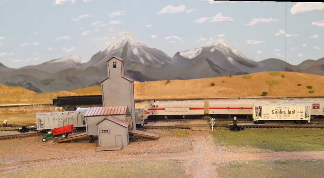
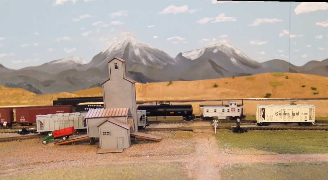
The layout was my Colorado and North Western. It was an imaginary layout, but was supposed to be in Colorado along the east side of the Rocky Mountains where the Chicago, Burlington and Quincy railroad once ran. (Now the BNSF)
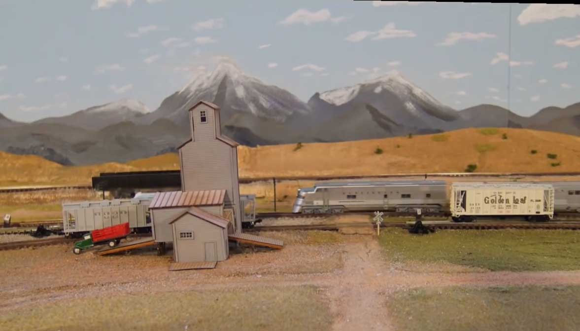
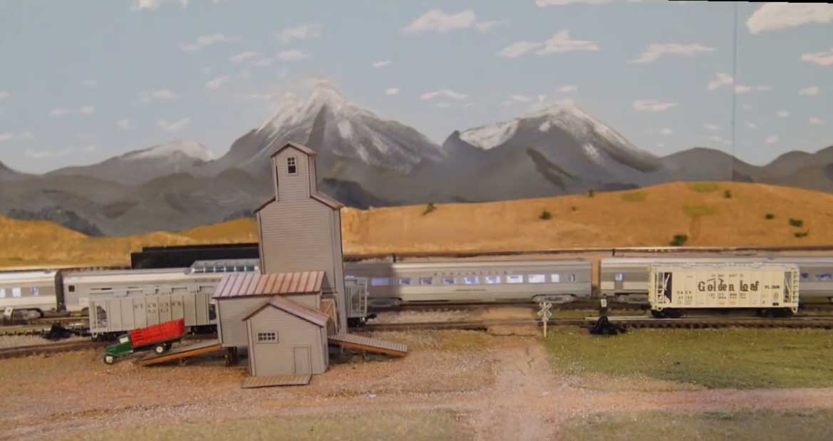
My locomotives were all CB&Q and of course I had the California Zephyr set representing the train shortly after WW ll concluded. The two locomotives in the video are an EMD E7A and EMD 3Fa & b.
The sound decoders were installed by Caboose Hobbies in Denver, Colorado before their change of ownership. They did a really wonderful job. The sound of the car trucks is enhanced with additional sound, but the locomotives sounds and noises are all from the decoders in the locomotives themselves.
This layout was N scale and the locomotives are about the size of my thumb. So they are very small but with a big sound.
Rob McCrain of Farland Howe”
Thanks to Rob for sharing his Burlington Vephyr model train layout.
You can see lots of more of Rob in the Hall of Fame.
Now on to Mike:
“Hi Alastair
I been following your posts since I started to build a model railway for myself and my grandsons. The railway is going well and up and running with me now working on the signalling and scenery. I have an electrical wiring problem which I am hoping some of your readers can help me with.
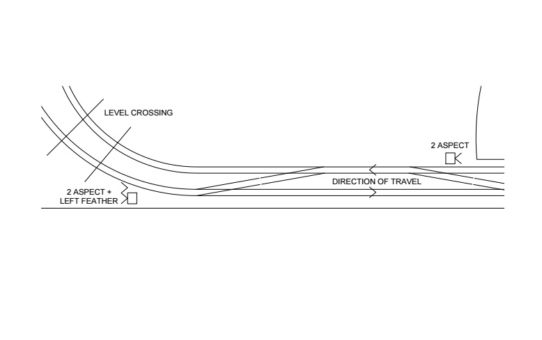
Attached is a sketch of one section which I wish to signal. The second sketch shows what I am trying to achieve.
Basically what I want to do is when the train on the outside track wants to go to the inside track I want the signal near the level crossing to remain red but the route indicator to light up, also the signal to the right of the second set of points should go to red. All signals are default green but can be changed to red when necessary by using the lever. I can achieve what I want individually but feel that this can be done just by using the points motor to activate the lights
I have not gone down the route of DCC, wishing instead to educate my grandsons in the finer art of playing with train sets.
Regards
Mike”
(Images are clickable)

A big thanks to Rob for sharing his Burlington Vephyr model train layout.
I just loved Rob’s narrative. It paints a wonderful picture, and also shows in heaps what this hobby is all about: having fun.
And on another note, who can help Mike? I know he’s opened a can of worms with his ‘finer art’ thoughts!
That’s all for today folks.
Please do keep ’em coming.
And if today is the day you decide to join in the fun, the Beginner’s Guide is here.
Best
Al
PS Latest ebay cheat sheet is here.
PPS More N scale layouts here if that’s your thing.


Mike,
I agree with you on the DCC question ;o)
My understanding is that you are trying to set up a kind of ‘passing loop’. The signal will have to go to red to stop the incoming train (a) before it is allowed to cross onto the inner track. There would be two separate operations although they could be combined.
You need to create a sequence of …
1) Stop the train at signal (a).
2) Wait, if necessary, for the inner track to clear.
3) Secure the line, stopping any other traffic (b) on the inner loop. ***
4) Send a message to the points motor to change the entry switch to face the inner track.
a) The point motor would need to change the polarity of the inner track having ensured that the exit switch is set correctly.
*** Item 3 can be done by the exit point motor!
*** Signal (a) must be set before the points are changed!
5) Perform the maneuvour.
6) Return all points etc back to normal.
I am not familiar withy the GM500 chip but it is probably a variation of the standard ‘PIC’ microcomputers. If so, it can be programmed quite easily with an inexpensive bit of kit that attaches to your PC.
This sort of operation is handled by British Rail when one track is being repaired and they introduce what is referred to as ‘Single Line Working’. In this case, a token would be handed to the driver who would take it to the other end and hand it to a controller or signaller. You couldn’t enter the section of line without the token – thus ensuring that only one train could be in the section at any time.
Hope this helps,
Alan McTavish …
Funny, very clean layout Rob. Enjoy your videos !!
DCC or not, I find that using a simple processor and doing all of the logic in software makes a lot of sense and gives incredible control and flexibility.
Mike; Just a comment on your signaling arrangement. To correctly signal both crossovers you should have four double stacked dual aspect signals, one pair located as in your diagram and the other pair located for movement through the second crossover in a mirror image of the first set.
Signal aspects:
normal mainline movement – double green or green over red with double red
on the reverse movement signal.
Crossover movement – red over green at entering signal and double red on the
three other signals.
Best of luck, Tim
Can’t be much help with wiring, but would point out that route indicators such as feathers are not supposed to light up until the main aspect is immediately about to show a proceed aspect (yellow(s) or green) for fear of encouraging the driver to think he’s getting a clear signal when it’s actually staying at danger.
Rod
Hi Mike. A very interesting track and multi-signal problem you’ve created. While complicated, I believe the directions provided by Alan M. would work. He certainly sounds authoritative on the matter. Good luck.
And Hi to Rob. I enjoyed your endeavor at giving life to your childhood reminiscence. I also enjoyed the look at the vintage EMDs. However, I believe you have a typo in the version of the E series loco shown in the video. That Burlington is an E5A. Nice work Rob with the sounds. — Arnie
As has already been pointed out, the feathers and the red light should not be on at the same time (other than for a very brief period just before the main aspect changes, which can be ignored for the sake of simplicity). The exception is if there is a subsidiary signal which allows shunting movements to proceed when the main signal is at danger. However for most situations what you need is a circuit which shows the feather when the main aspect is set for green and the point is set for the diverging route. For this you need to switch your main aspect using a single pole double throw switch (SPDT – one with two sets of contacts).
For the second question, you need the manual signal switch and the point switch(es) in parallel so either can switch the signal to red.
Thanks for posting
What a wonderful narrative of the influence trains have had on your youth.
It is interesting how important trains were, and still are as we experience life.
I will often stop my car to gaze at an interesting train trestle, or watch a passing freight or passenger train as it disappears down the track.
Thanks for posting your video and narrative.
Gratefully Sal from New York.
Hi Al
Thanks for all the long hours you must put in to bring this blog to all our doors, I find absolutely fascinating. The informative videos, reports and comments are exceedingly helpful.
When I have a signalling and loop polarity issue or in one case, keeping a complete loop separate with four sets of points to enable dc (analogue to run on the loop) but allow dcc to be used on the rest of the layout. Swapping from dc to dcc on the said loop when wanting to do so.
I use a simple logic PLC (programmable logic controller).