John’s been in touch with his ho scale switches and turnouts:
“Al, Copy-cat John here.
I want to share with you a test project I just completed to insure it would work as planned.
I have two turnouts on my yet to be finished HO layout. I decided to use manual Caboose throw switches. Boy they look so much bigger on the Internet. The two turnouts must coincide with each other. I was concerned at a distance how would I know if the two turnouts were in sink with each other.
I watch westerns on TV where the train man comes out to the track and moves the switch handle for the on coming train and then he goes back to where ever he was. I always wondering how did they know if the track was set correctly for the next train, without going out and looking at the switch. I devised a system using LED lights, a push-on push-off switch and a 12 volt automotive Relay.
I made a cabinet to house the push button switch that I hope looks like it belongs next to a train track. This cabinet in two parts, the bottom has the push button switch and the top slides over the bottom with an aspirin like button in the under side of the top which makes contract with the push button switch.
A 12 volt adapter provides juice to a particular terminal (#30)of the Relay and comes out of another terminal (#87a) which in my case goes to a “green” LED light beside the turnout indicating that the turnout is in the straight position.12 volts is also going to the push button switch and when the switch is activated it sends juice to terminal (#86).
When terminal #86 receives juice , terminal #30 is no longer connected to #87a (tuning off the “green” LED light) but instead it’s now connected to terminal #87 which in my case turns on the “red” LED light..The concept is that if I see a “green” light at one turnout and a “red” at the other I need to change one of them.
I hope the pictures below will make this a little more clearer.
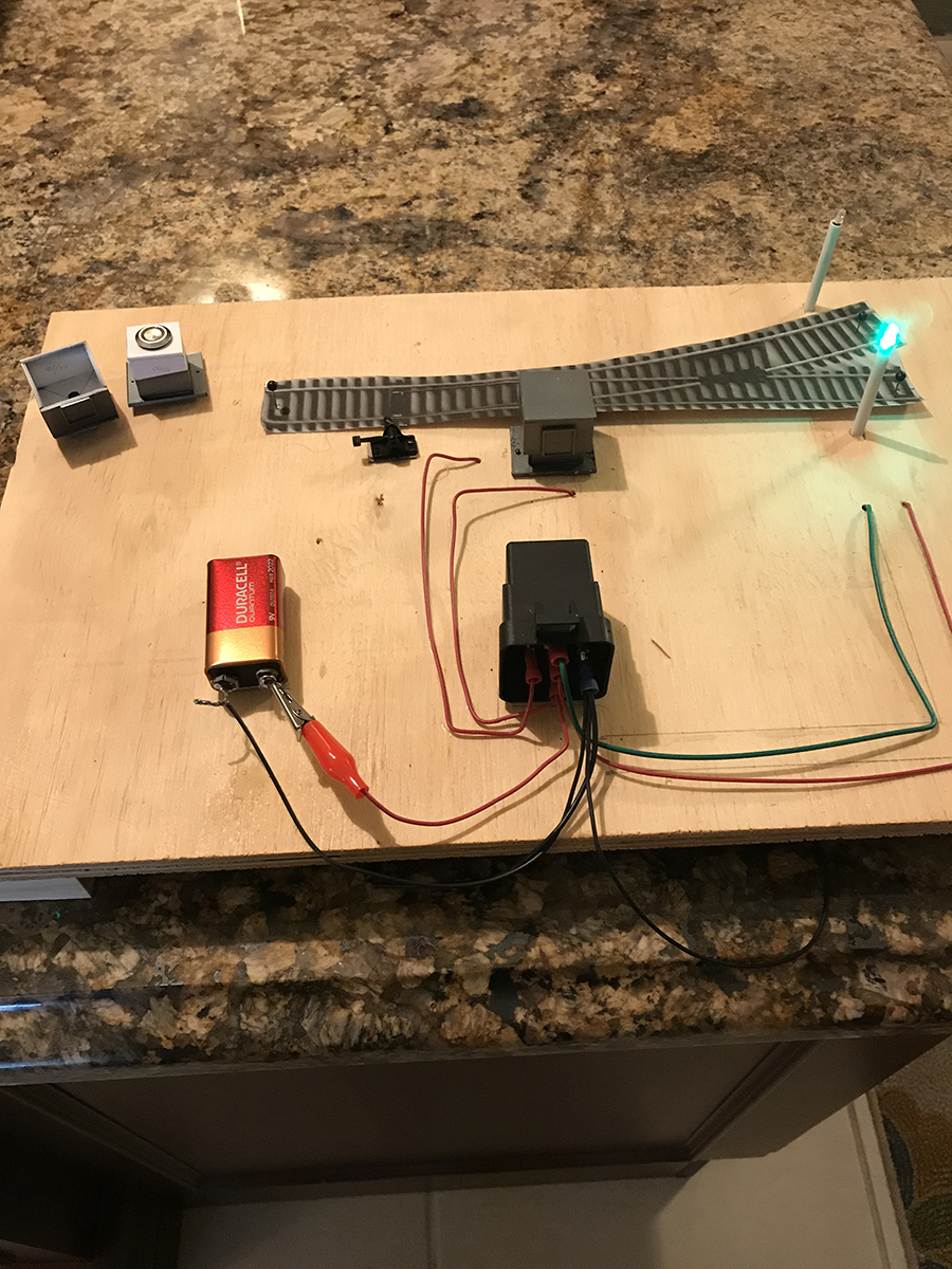
The first picture is the test project using a 9 volt battery. On the left top corner is the second switch cabinet. The top is upside down to show the aspirin like button that touches the push button switch, You have to assume I have thrown the Caboose throw to move the turnout to the straight position and pushed down the cabinet to turn the “green” LED light on.
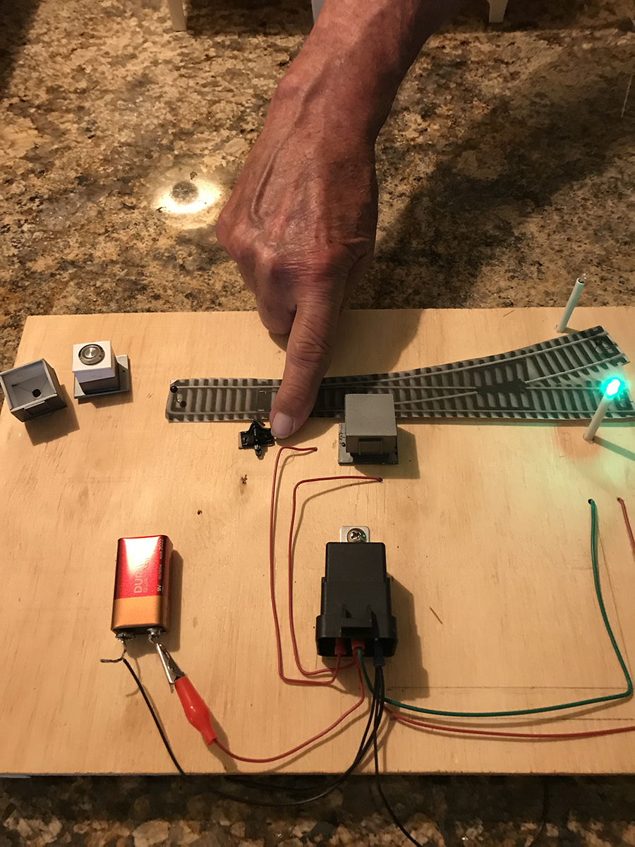
The second picture shows me changing the position of the Caboose throw to change the turnout to the curved position.
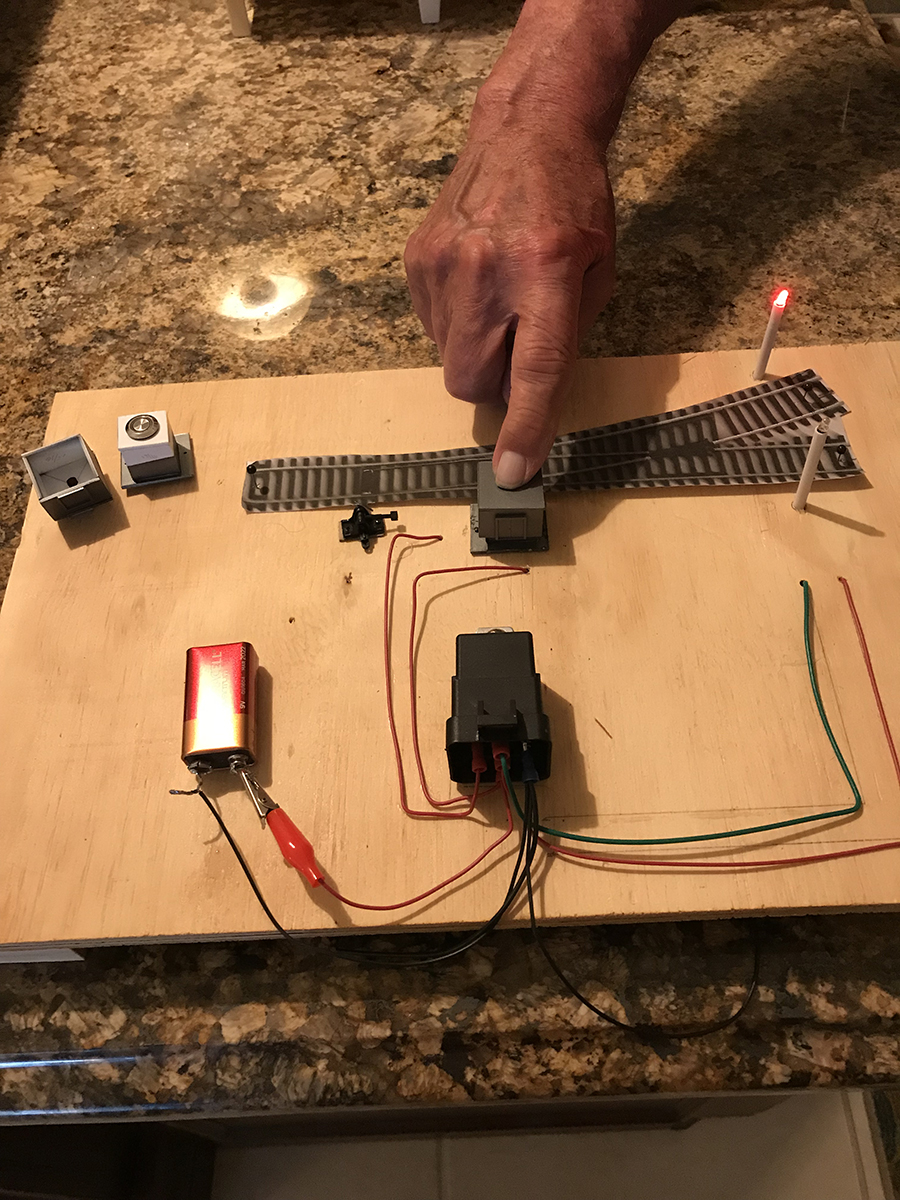
The third picture I am pushing down the cabinet to change the light to “red”. I plan to have these LED .
John”
A big thanks to John – his last post is at the bottom of this one.
Now on to Rob:
“Hi Alastair,
Thought you might like this video. I go into the various parts of a point, turnout, switch which some of your subscribers might find interesting.
Rob”
Latest ebay cheat sheet is here.
A big thanks to Rob and to John for sharing his HO scale switches and turnouts.
That’s all for today folks.
Please do keep ’em coming.
And if today is the day you get started on your layout, the Beginner’s Guide is here.
Best
Al
PS Latest ebay cheat sheet is here.


Rob, love your layout, so detailed and all trains running smoothly. I have watched a lot of your videos and I am amazed how you have progressed. I guess you must be a natural with a good eye for detail. Keep it up.
John, I understand what you are doing with the turnout status indicators, but wouldn’t it be better to build them into a track plan control board, where the operator could see the status, without having non prototypical status lights on the track, you could then automate the turnout operation at a later date should you wish too. Love your approach though! Regards Peter
John
Love what you did. My approach though is to put the push button on a control panel with idiot lights because of the number of switches and to avoid confusion. Reg/green indication at the switch the way you show it is really nice so now I have to add it.
Rob
Much appreciated and admired.
George from NY
I have been kit bashing model railroad buildings, working on my outdoors slate quarry railroad for years – over 80 now – and never wear these rubber gloves. What is it with modelers today that they are afraid to get their hands dirty?? Never wear gloves except in the winter to keep my hands warm.
HI from sunny Florida
I am doing the same thing with my lay up tracks. Using Leds I can tell Which way the switch is and where the train came from and where it goes after the run. Green to pull the train out and the power on the layup and red to reverse the train back into the layup. Not using batteries but the track power and a push button to give power to the track, When the run is over release the button and power is cut off and the next train pulls out. I am doing this for 5 layups on of which will have a track cleaning train.
Thank you Copy Cat John…..Thank you for sharing Mr Howe. Your layout is amazing. Great work !!!!! Paul Ohio USA
Rob sounds American, but his railroad obviously is not. Where is Farland model RR located? Thanks
Hi John
Why not using a reed contact and a magnet under the loco. It’s less costly and invisible to build in. You don’t need a relais that can switch 20 amps
Great stuff Rob, but those yellow and flashing red wigwags are used for public roads with or without lifting barriers. A farm crossing between two fields on a busy line would usually have just telephones for anyone needing to cross to ring the signalman for permission.
Rod