Jerry has been in touch with his thoughts on Wiring DC and DCC:
“I had not thought much about ‘difficulties” in wiring a model train layout until I read one of your recent publications.
Comments made to answer the question posed kind of developed into DC versus DCC.
A few comments did provide some advice as to wiring but no one bothered to provide any wiring diagrams for the questioner.
Wiring a model train layout can be a real challenge or it can be relatively easy. Ask yourself the question: what type of train operations do I want to do?
For me having a train go round and round on a loop seams rather boring, but very easy wiring.
My first layout I built was about 1956. It was a 4 ft x 8 ft piece of plywood and a oval track. Since then I have constructed a number of layouts.
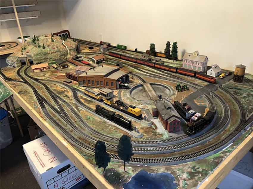
When we moved to Utah, USA, a few years ago, we found that our home would not accommodate a train play area. So we purchased a 12 ft x 16 ft shed, Grandpa’s Train Room.
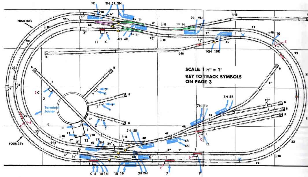
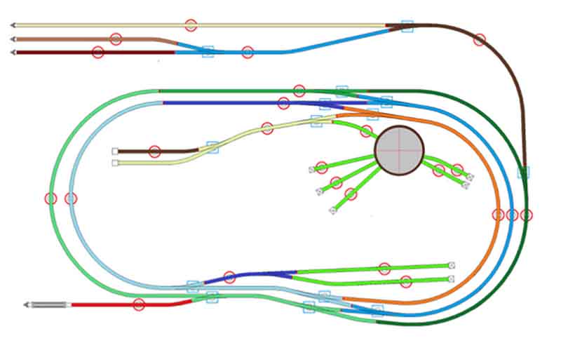
Like I said, having a train just go around a loop did not seem like a great challenge. So I chose the Atlas “Great Eastern Trunk” layout [with modifications] for my layout
I can run both DC and DCC on the layout. Electricity is electricity, whether DC or AC.
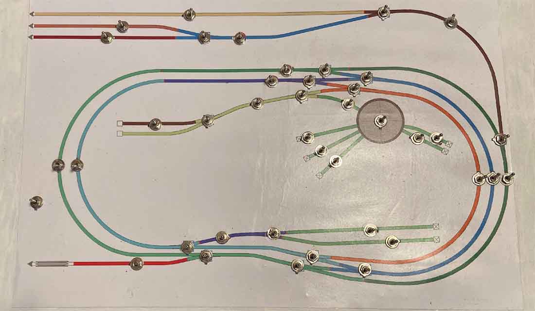
The layout as wired has 15 sections of track operated by DPDT [double pole double throw] center off switches.
There are 15 turnouts operated by SPST center off switches.
Also, since the turnouts are AC operated I have inserted one DPDT center off momentary switch (So anytime I use a turnout switch I don’t accidentally leave it on which could burn out the turnout mechanism).
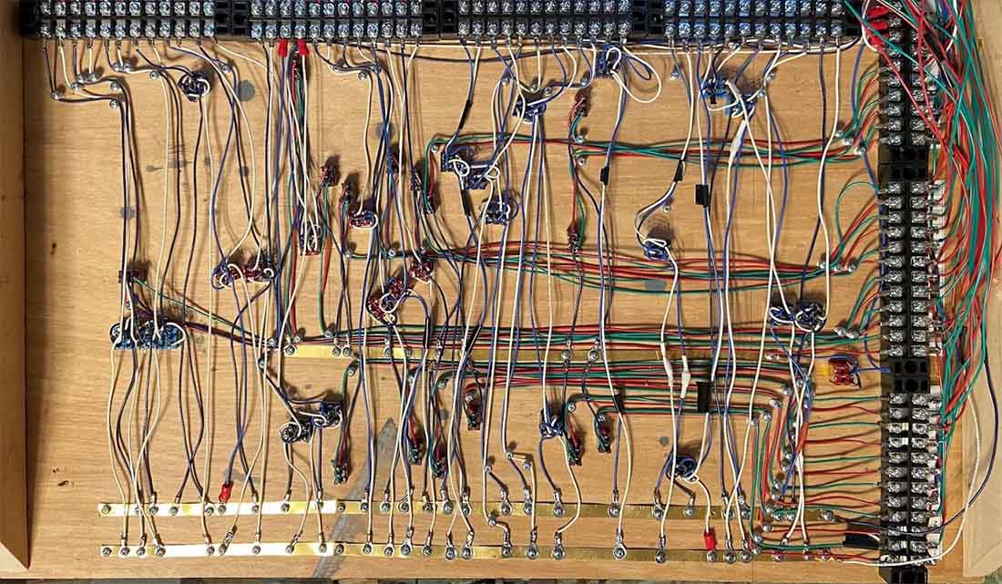
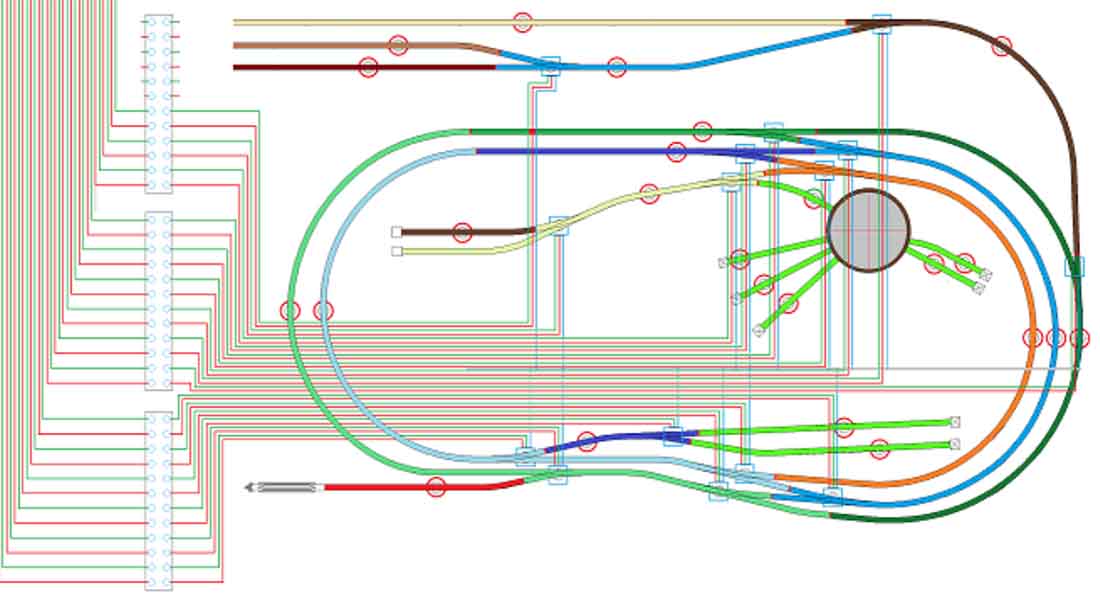
This is the under side of the control panel.
Now I can run either [but not both] DC and DCC. I just have to remember to switch the track switches [all] to either clockwise or counter-clockwise position.
I do not operate the turnouts by my DCC controller only use the SPST switches [+ momentary switch.]
Below is the turnout switch wiring.
I hope this helps with wiring issues.
Jerry”
I’m not sure which post on wiring Jerry means, but it could be this one:
Wiring your model railroad layout.
Now on to John:
“Hi Al
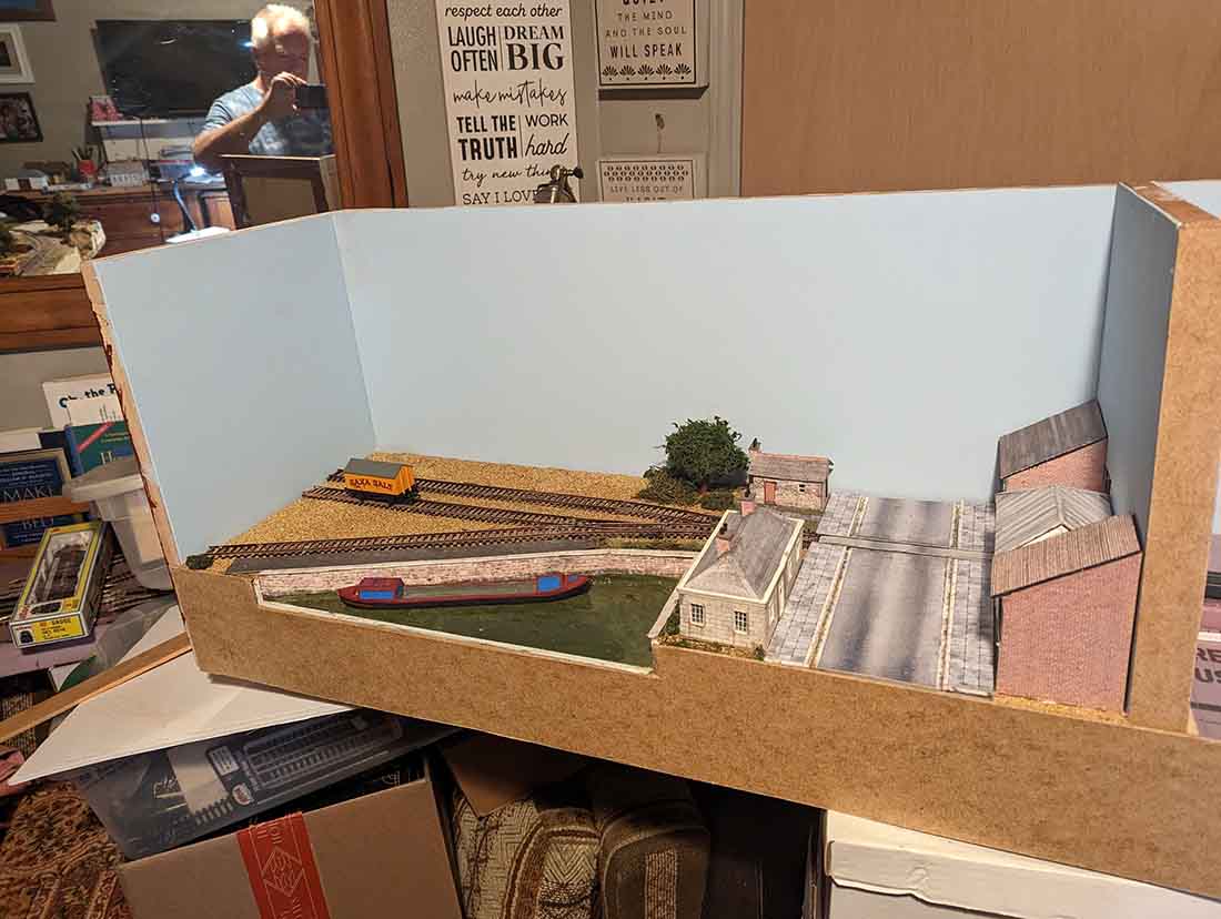
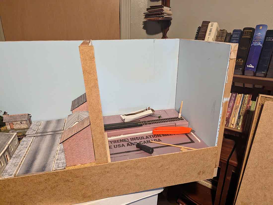
Thought that you might like an update on my newest layout.
I have not settled on a name yet.
Rose Lane maybe? Quay House Road?
Anyway…
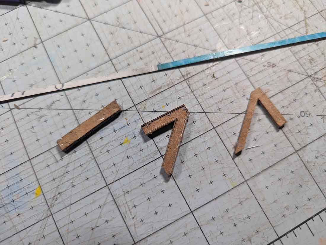
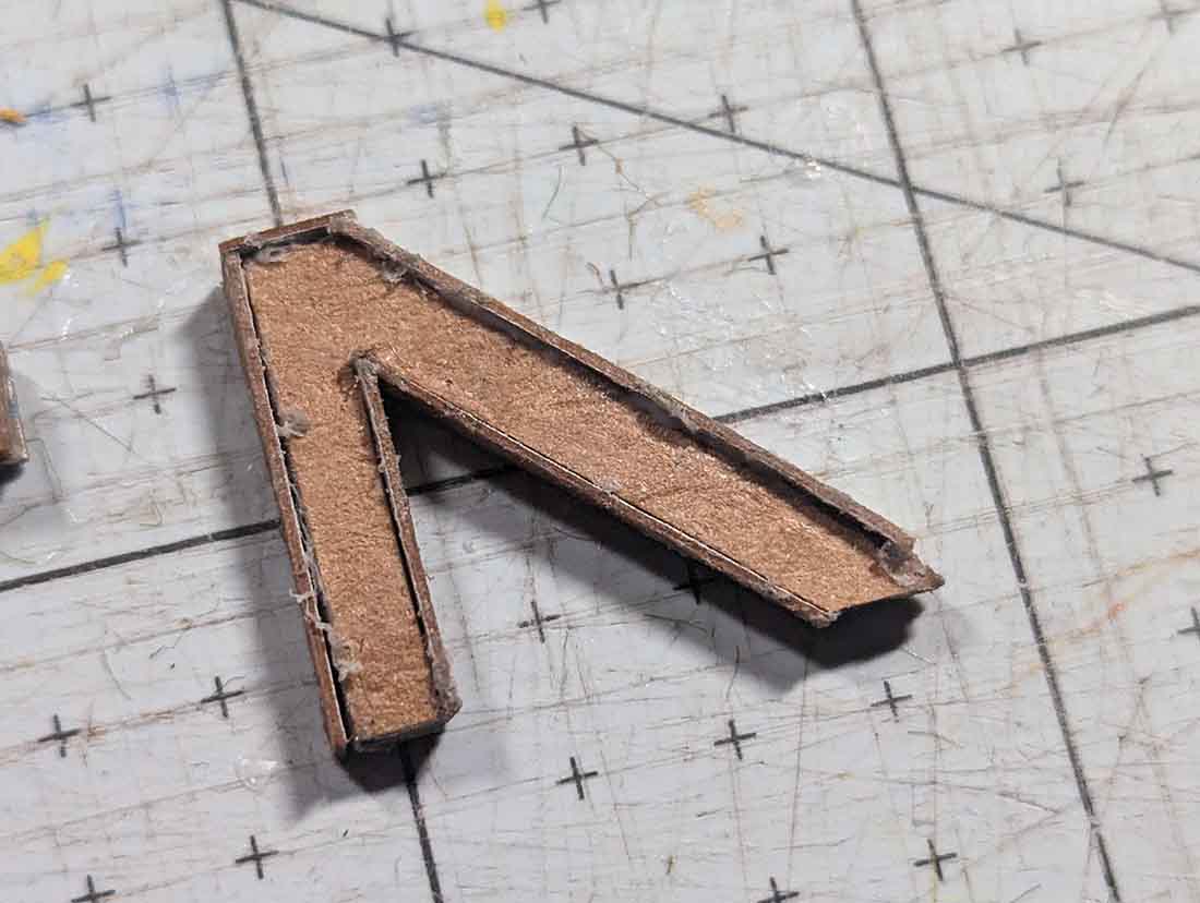
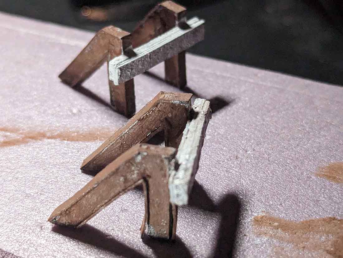
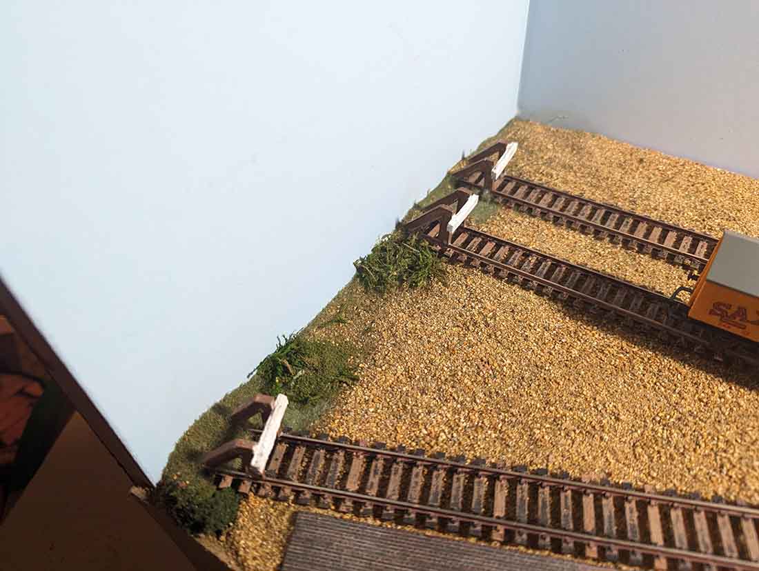
I have a boot of a back scene up and a few other details to tidy things up. The most fun was making my buffer stops though..
Ordering the stops and waiting for the post did not seem like an attractive option so I made my own.
All the best,
John”
John’s last post is here.
A huge big thanks to John, and to Jerry for sharing his narrative on Wiring DC and DCC:
That’s all for today folks.
Please do keep ’em coming.
And if today is the day you clip boredom around the ear and join in the fun, the Beginner’s Guide is here.
Best
Al
PS Latest ebay cheat sheet is here.


I’m just starting to layout my electrical – lighting and switch control, allot of work, but to do it right it takes time. I tried to rush it a bit and was told that building the layout and everything that is included should not be rushed. Part of the enjoyment should be the build., and I now agree Great job
While I have mostly servo controlled switch machines, I still have a number of AC solenoid machines for yard tracks. A few quick comments for Jerry. 1) since all the solenoid switch machines have the same common, I run that wire all over the place, and have a single terminal common to all the control switches back at the control board. 2) I have spring loaded DPDT switches, center off so burning up the coils is not a problem, the second set of contacts go to little relays that light LEDs – green for normal traffic, red for divergent. I like the color-code for each track block on the schematic on the layout control board, good idea. I’m working out a way to have “matching LEDs” where blocks connect so I can see if my locos will run across or stop because the direction switches for the next block is set backwards from the one the loco is in. Will send what I come up with when I get around to it. Good job Jerry, wiring is tedious and back-breaking!
John from Baltimore
Hi Jerry,
You did a great job detailing and explaining the process.
Thank you, Jim
The installation of the “master” momentary toggle switch is beautiful!!!
I visited a CTC facility on the AT&SF a long time ago and they demonstrated how they could set a route up on the board. When it was all established, the operator pushed an enabling button that sent the appropriate message to the apparatus in the field, this time about 60 miles away. and then the reset the board and pushed the enabling button again and it was all back to the original setting. The operators laughed and said if there was a maintainer up on Raton Pass, he probably was wondering what just happened.
I remember that visit, but never thought about a model RR application till now. by using double pole switches, an indicator light and or line side signals could be operated too.
Al, I enjoy what you do for the RR modeling community. But the last post on DC and DCC wiring only made it more confusing. More and more people are going to DCC; so unless DCC wiring is explained very clearly and extensively especially on DCC and DCC reverse loop wiring on various layouts, it prevents people from continuing their forward progression in RR modeling.
Try to post many more posts on these issues. Thank you.