David’s been in touch with his industrial model railroad:
“Alastair:
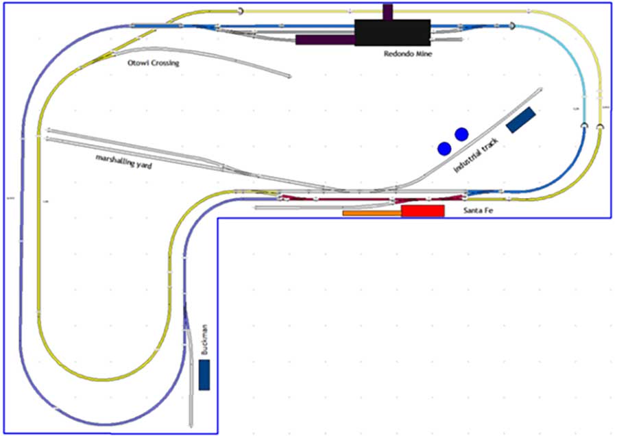
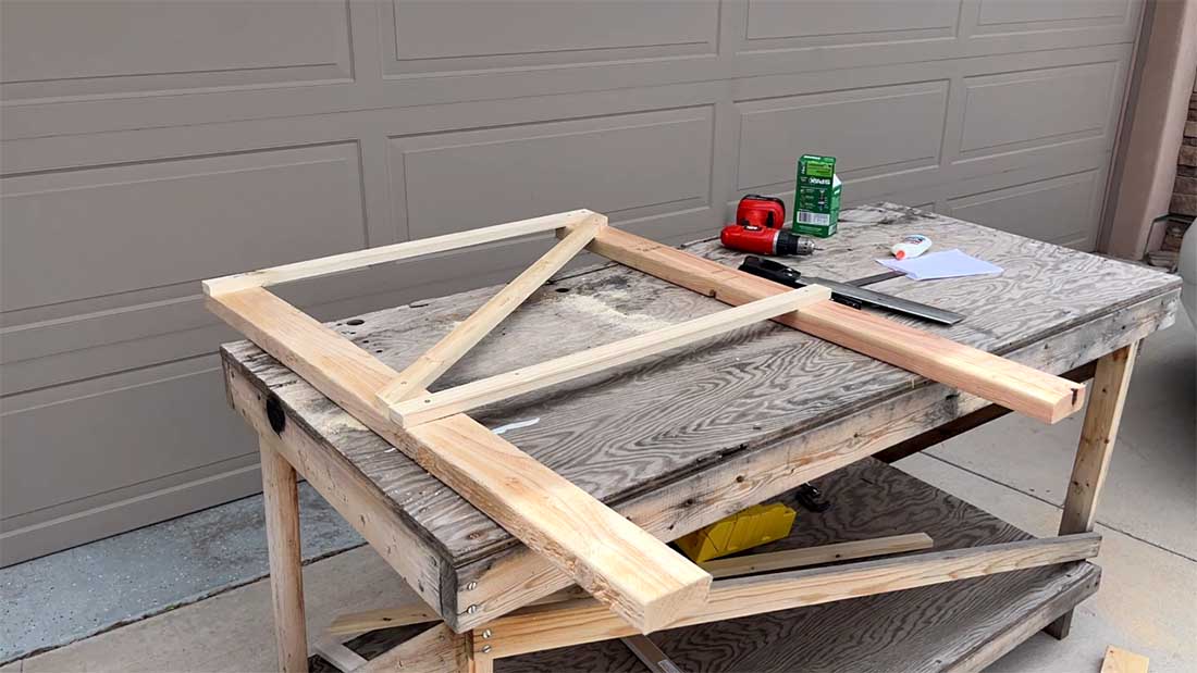
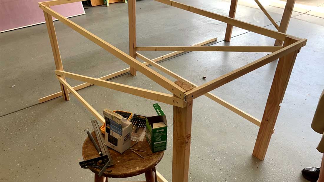
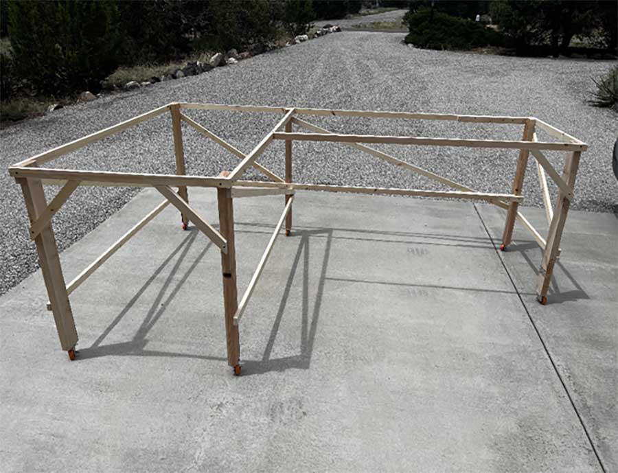
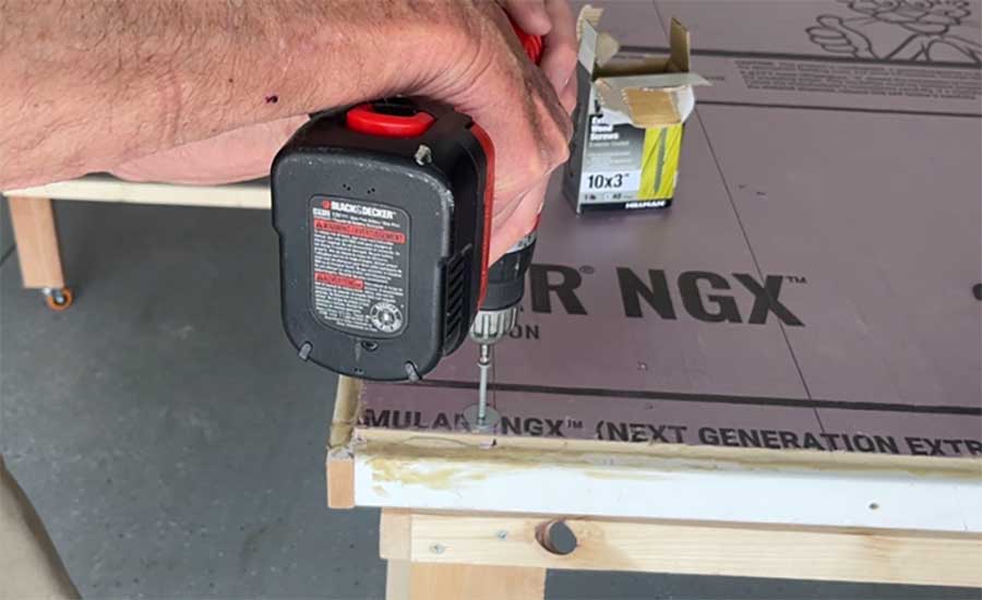
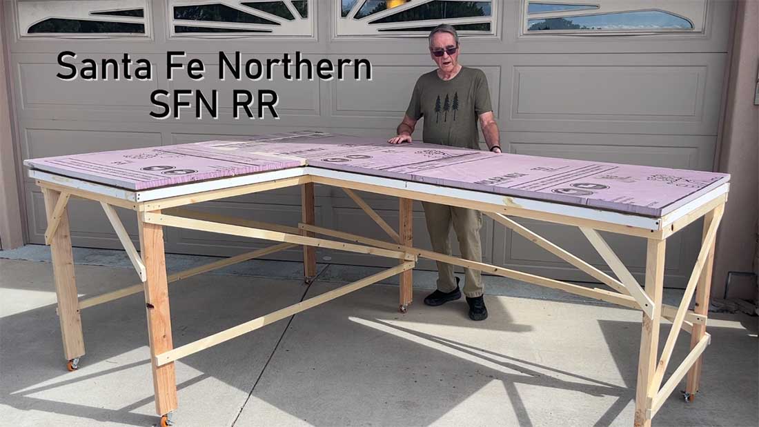
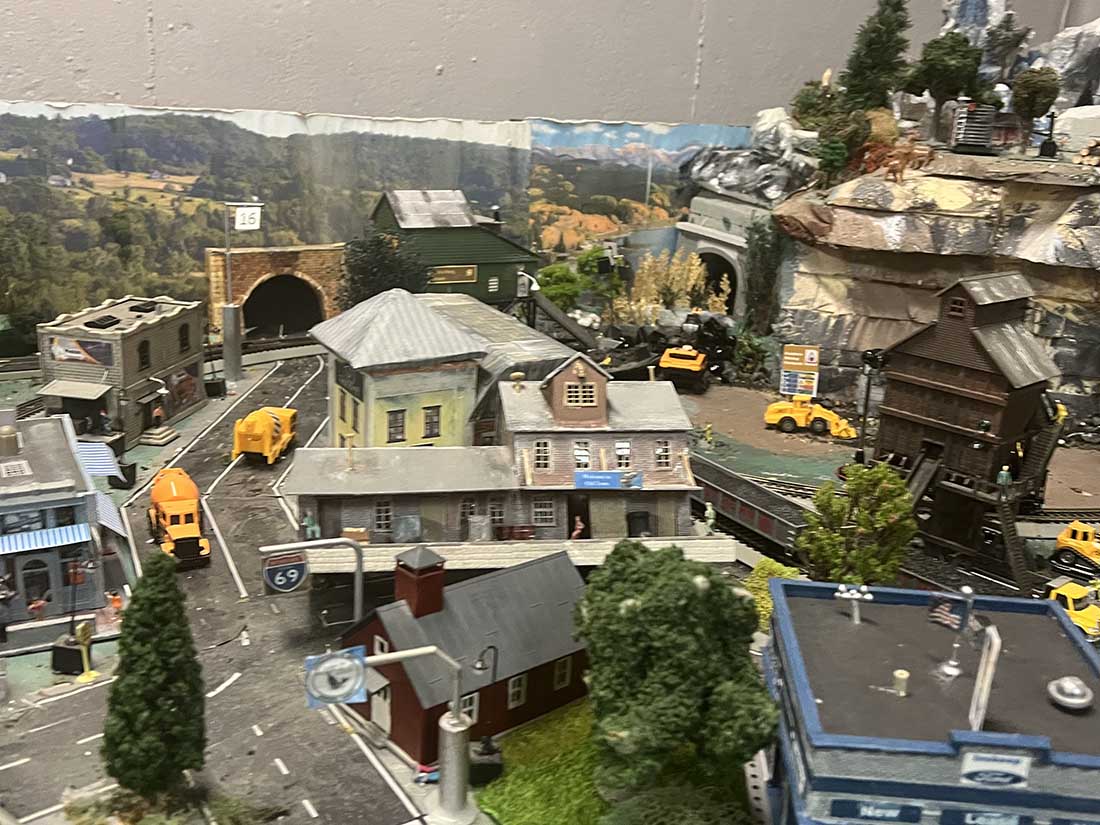
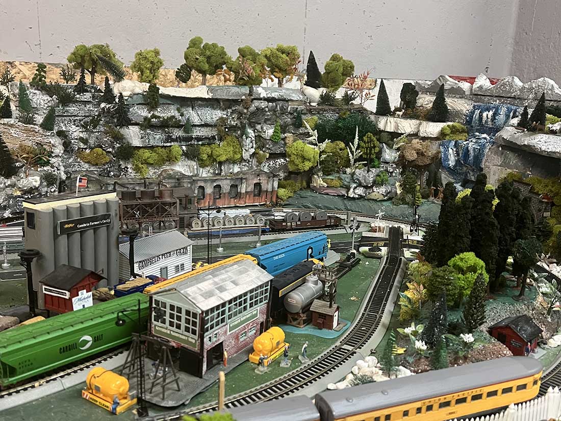
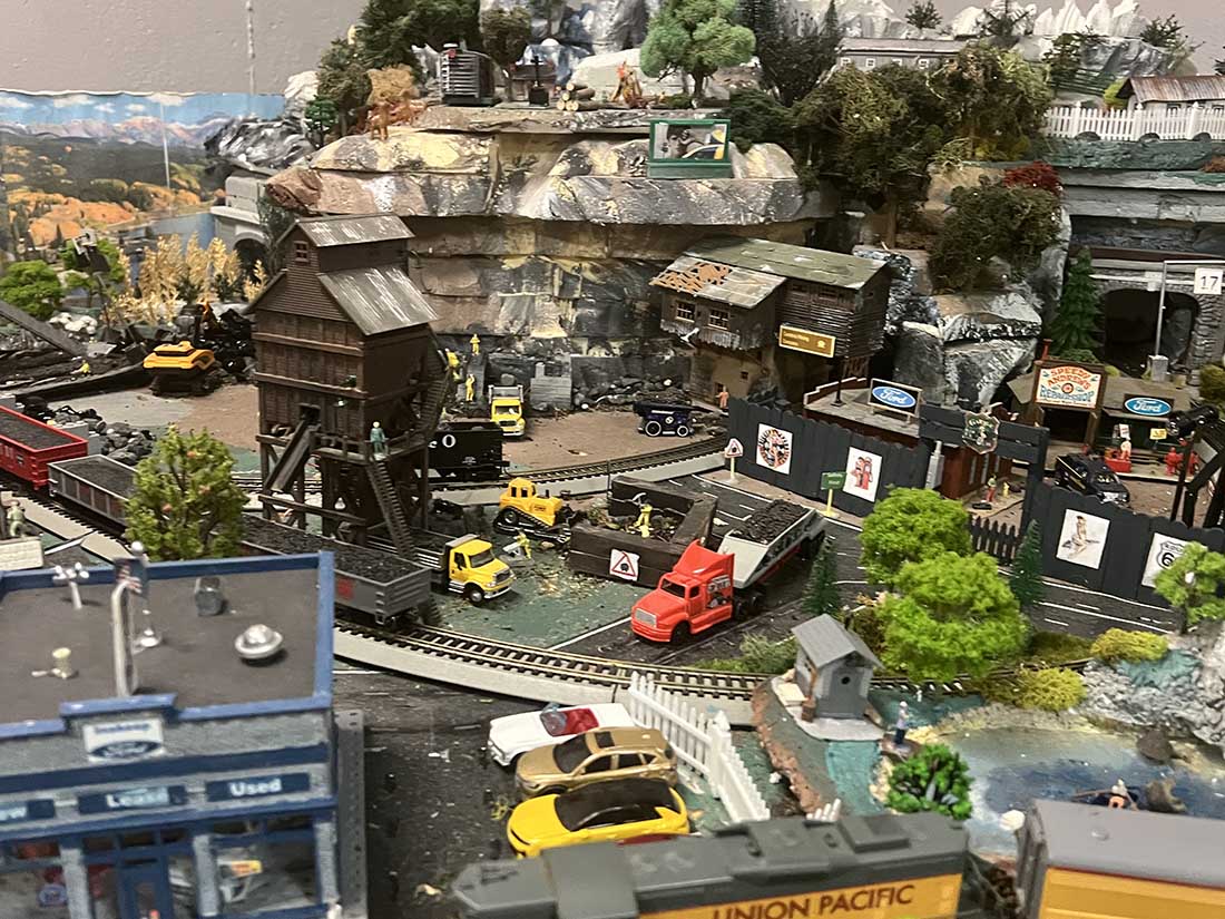
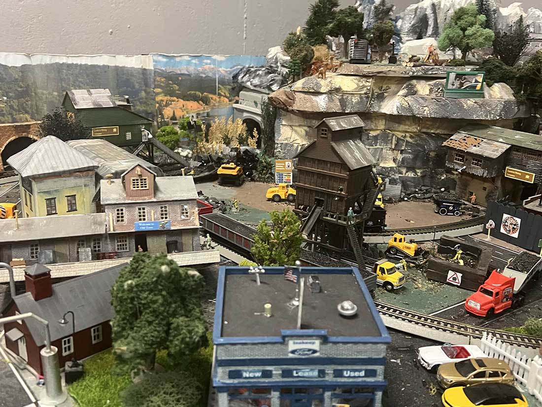
Since I last sent you photos, I have taken on two projects. The first is expanding my HO layout with an industrial yard. My HO layout now extends approximately 15’ x 15’.
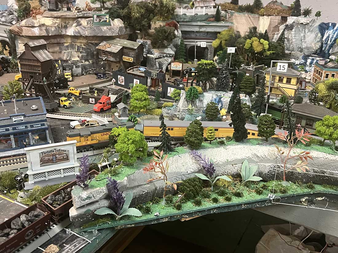
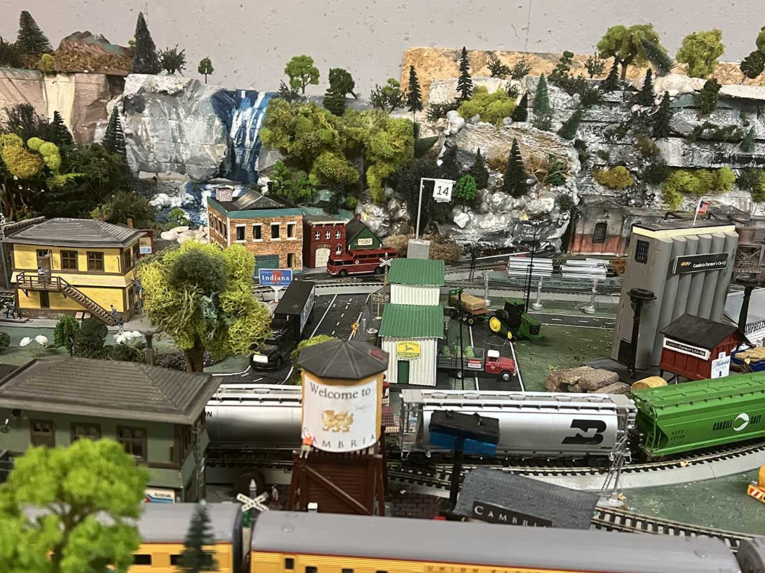
My HO layout is not proto-typical, but it does honor the small businesses in my town of Greenfield, Indianan and two of the adjoining towns.
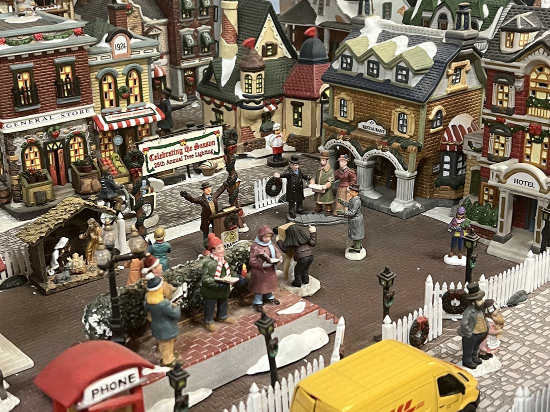
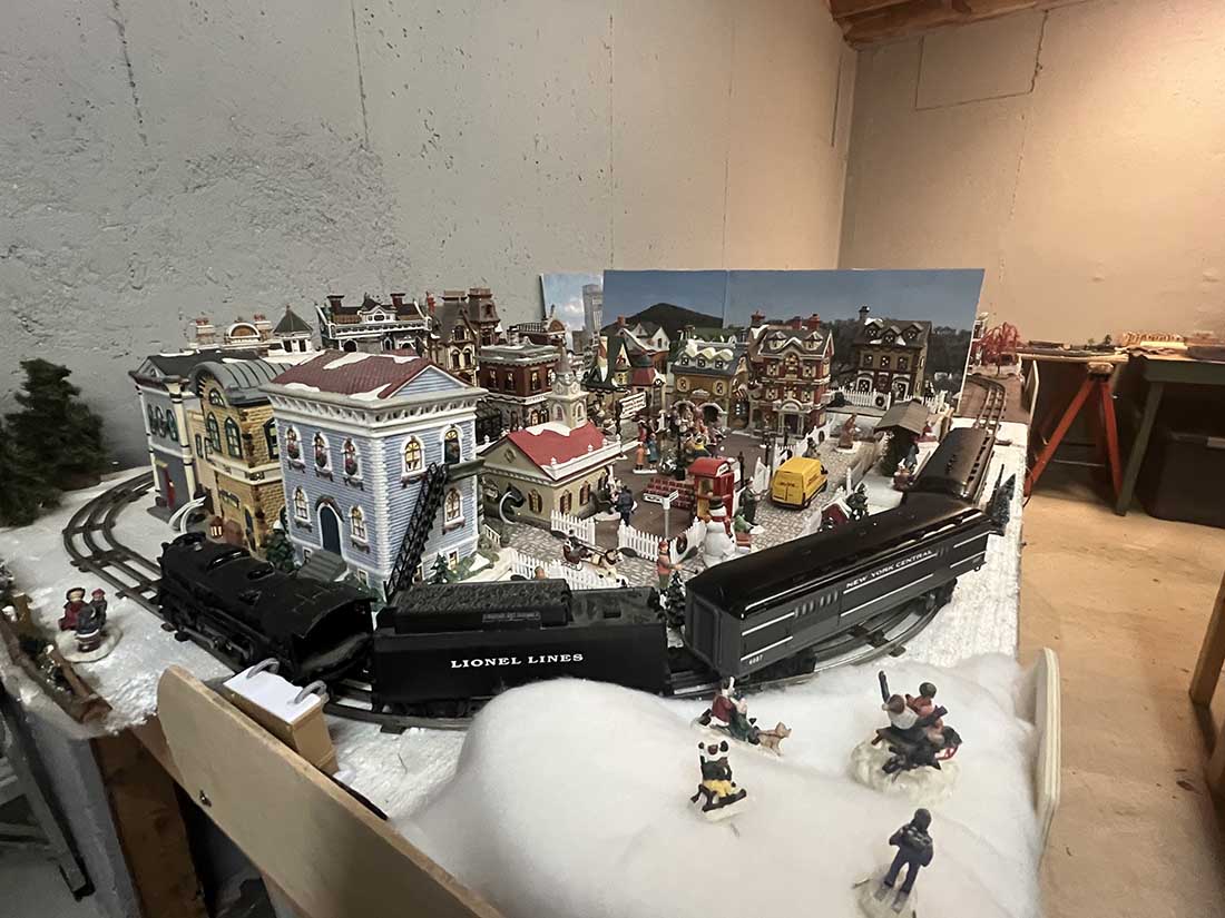
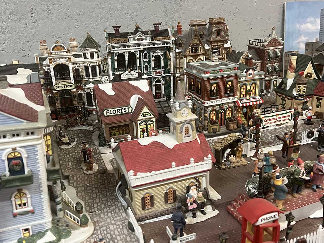
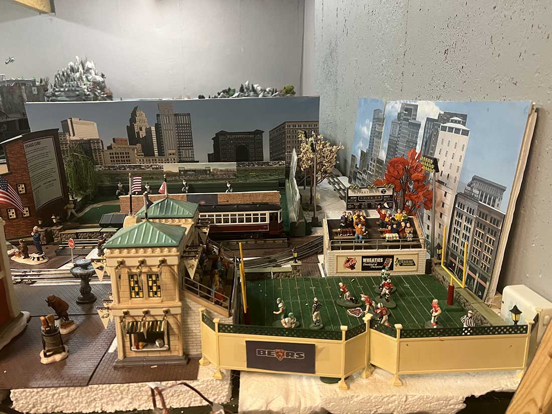
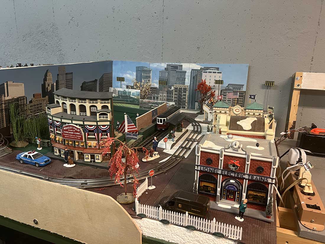
Second is that I have revitalized the remnants of my 027 gauge Christmas Village with an adjoining section for Wrigley Field and Soldier Field (Department 56 porcelain structures).
I am originally from Chicago. My 6 an 8 year old granddaughters have taken a liking to my trains… who would have thought?
David”

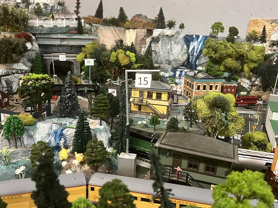
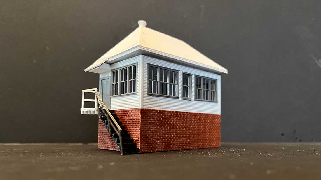
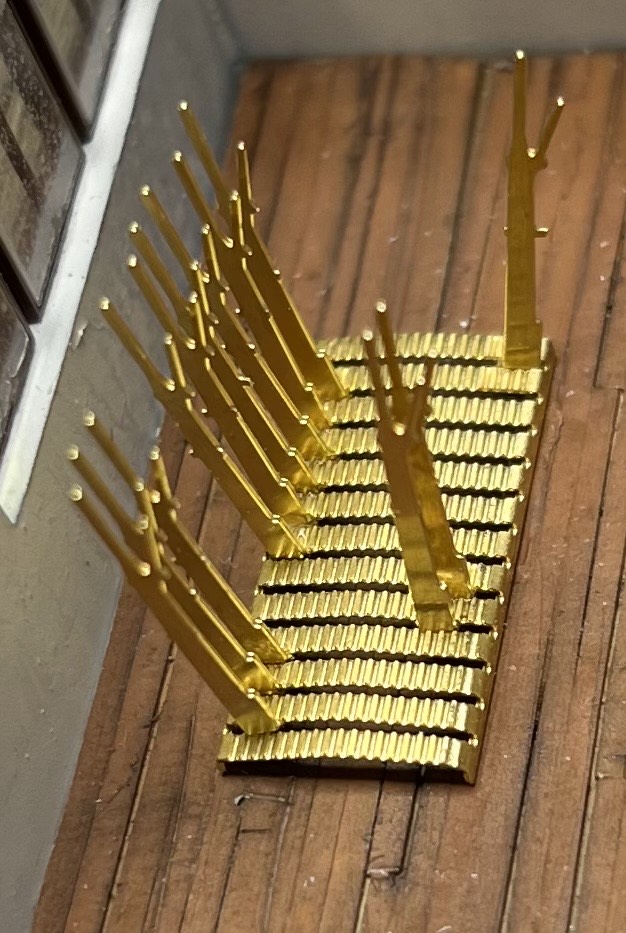
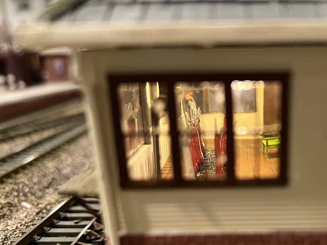
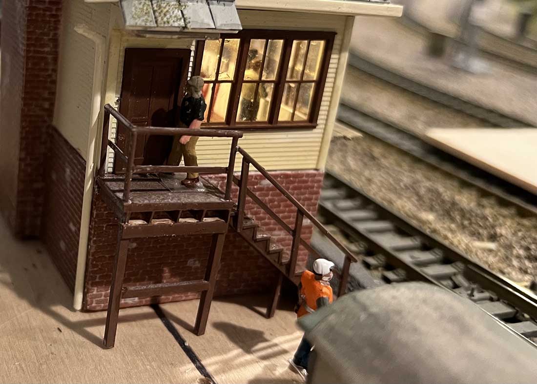
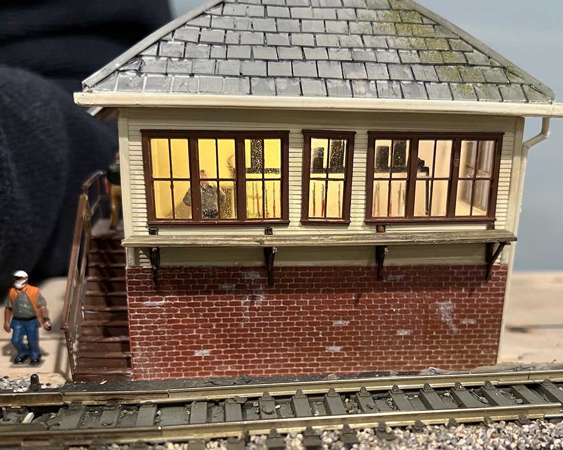
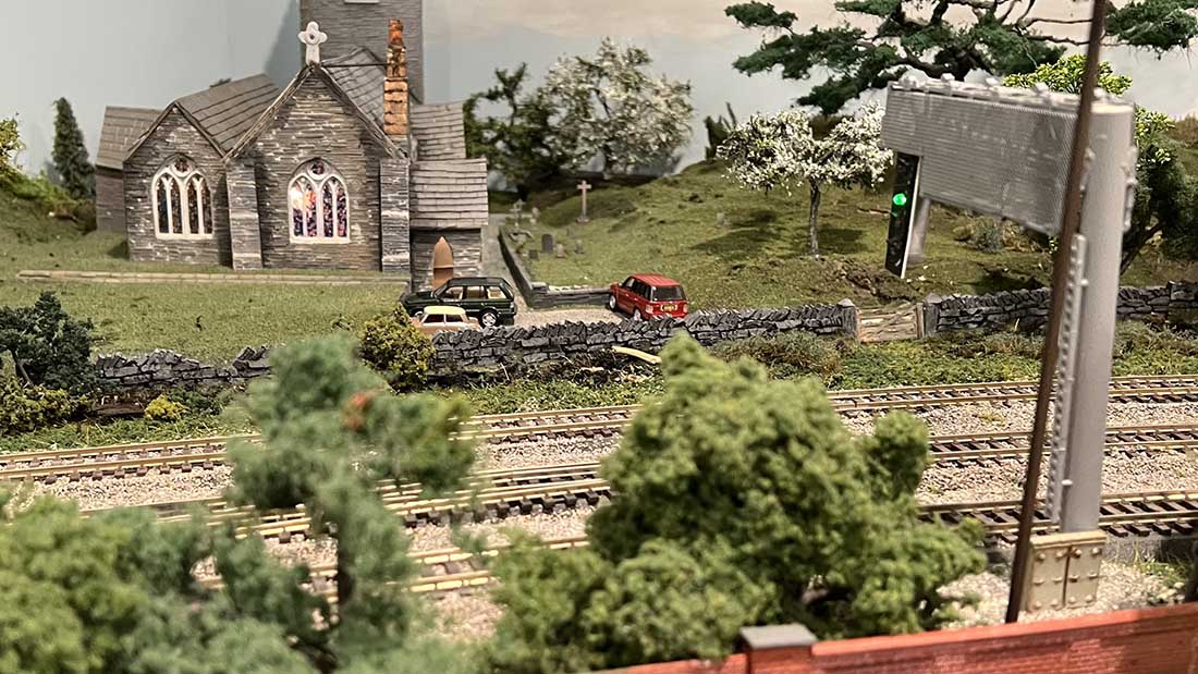
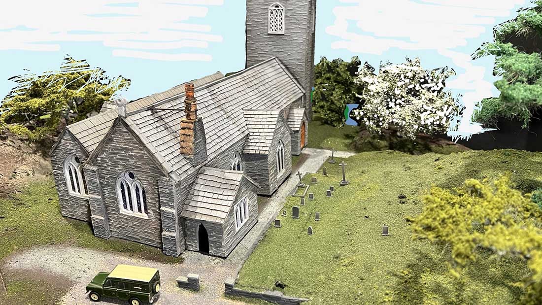
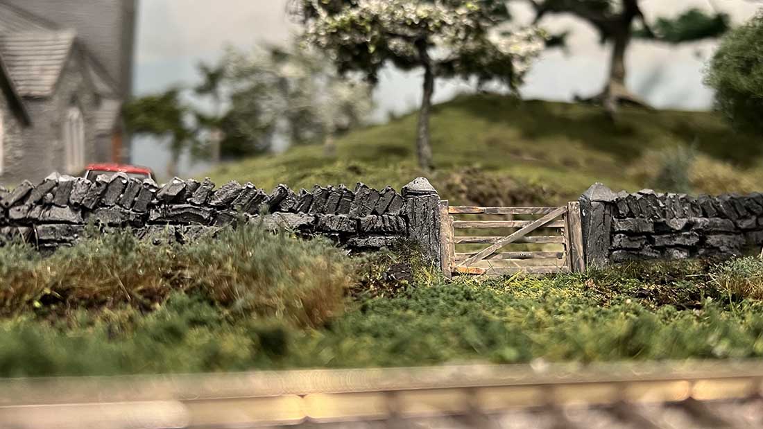
And David’s O scale:
A big thanks to David for sharing his industrial model railroad.
You all know how much I like a layout with a theme, and industry is a popular one – there are a few that spring to mind.
HO Walthers Industrial substation – John’s layout is fabulous, it looks great fun.
HO scale industrial layout. Carlos from Portugal has a great layout with freight, logs and coal.
Industrial HO scale I do like it when you can see a layout from start to finish.
Don’s steel mill is another one too.
Then of course, there is Hall of Fame Fred’s N scale facory, which is just on another level. Have a look and see:
(You can see more of Fred in the Hall of Fame.)
That’s all for this time folks.
Please do keep ’em coming.
And if today is the day you get started on your layout, the Beginner’s Guide is here.
Best
Al
PS More HO scale train layouts here if that’s your thing.
Need buildings for your layout? Have a look at the Silly Discount bundle.