Ben’s been in touch with his model train large trees – enormous ones in fact:
“Alistair,
I am starting a HO scale layout of Pacific NW logging using around 1900 as the time I want to represent.
I have started making Giant Redwoods and Giant sequoias for this. I have found that many confuse these trees as being the same and model them incorrectly.
It turns out they are completely different tree species. I have a prototype model of a Giant Sequoia found in Oregon and sometimes in California and I am working on a prototype for a Giant Redwood found in the northern coastal region of California.
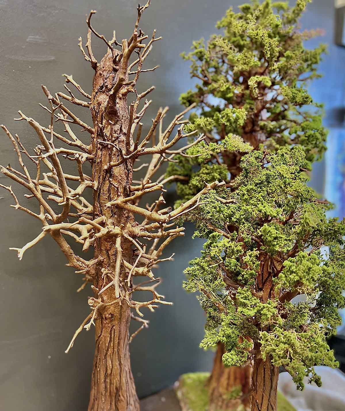
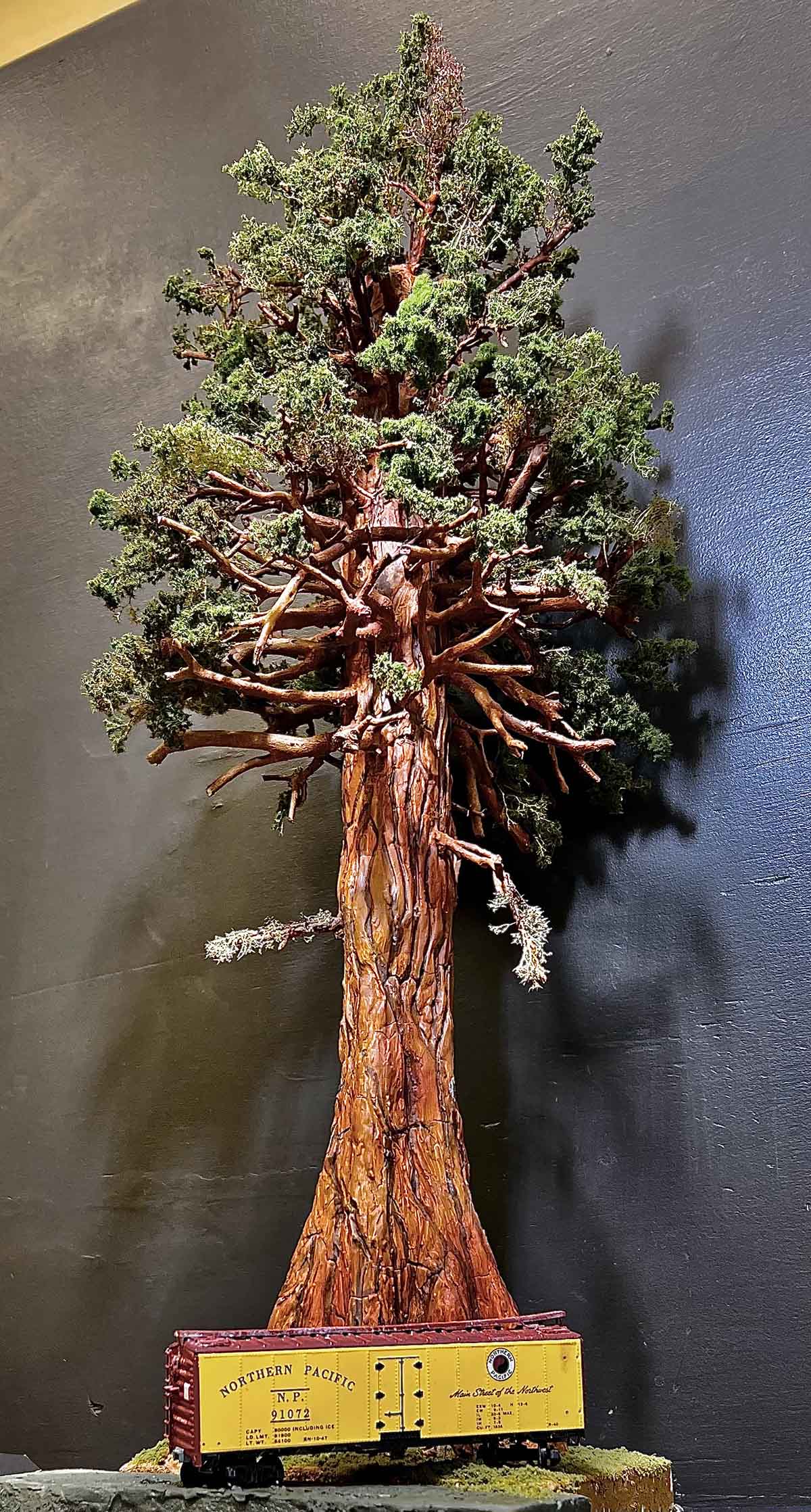
This shows on the left the basic structure of Giant Sequoia w/o foliage; center right is smaller completed Giant Sequoia.; on the left is the trunk of a Giant Costal Redwood. Note differences in bark and trunk configuration. Can send building details if desired.
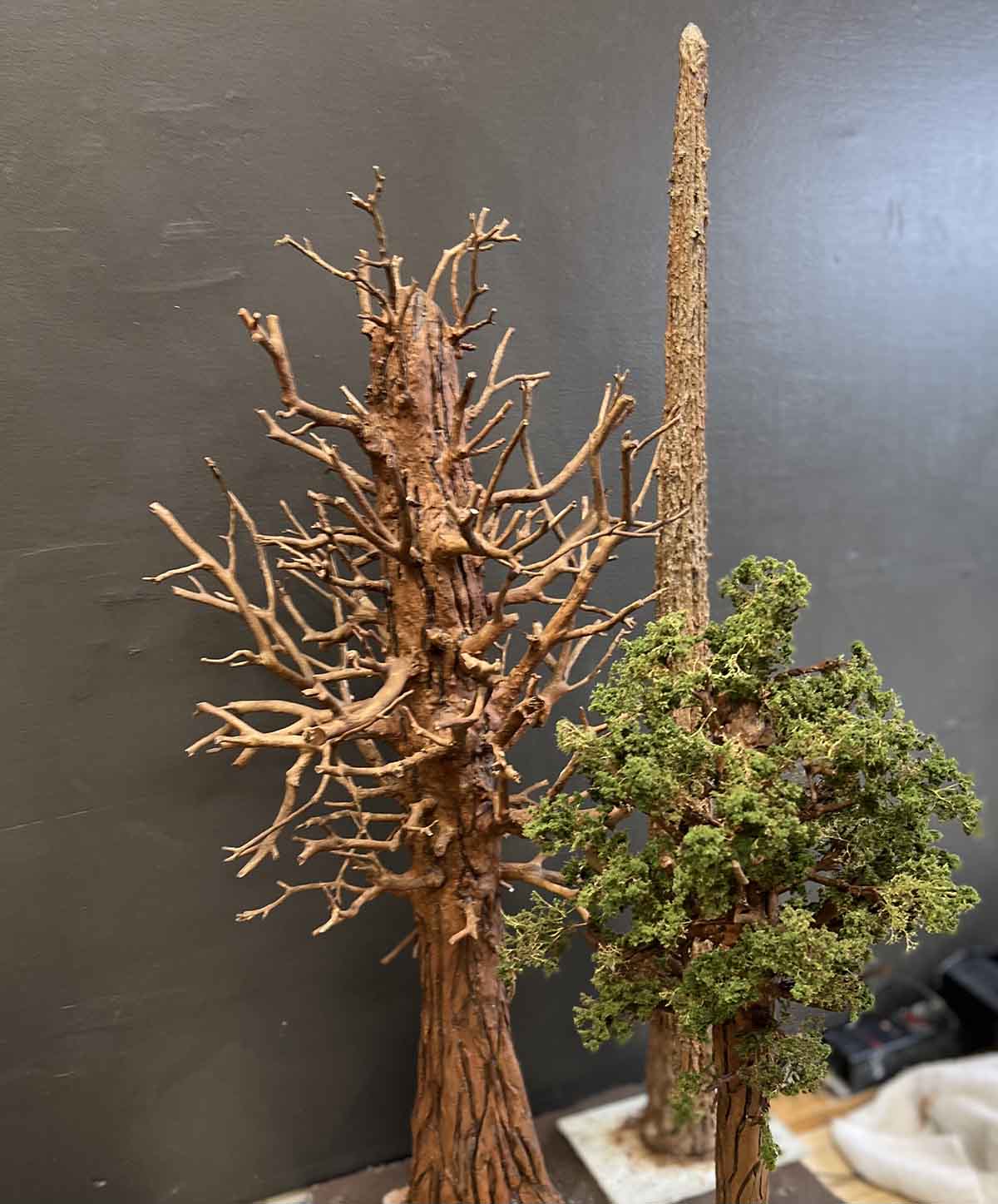
On the left, trunk and limbs of Giant Sequoia before foliage and on the right are two Giant Sequoias with the smaller of the two in the foreground. Details if desired.
This is a scratch build Giant Sequoia. 24” tall, so 174ft. in HO scale.
Thanks,
Ben USA”
Model train large trees? They look enormous, just like the real thing! A bog thanks to Ben.
There’s lots of tree posts on the blog – Rob’s how to make trees springs to mind.
“Hi Al,
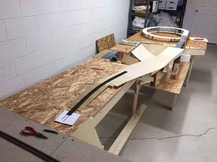
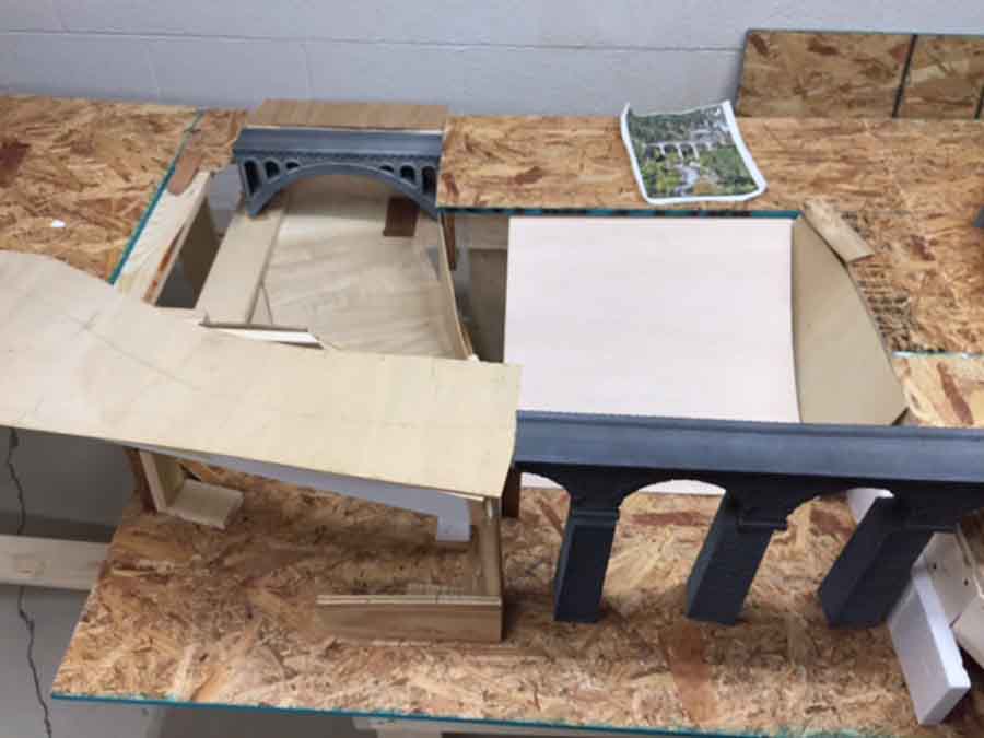
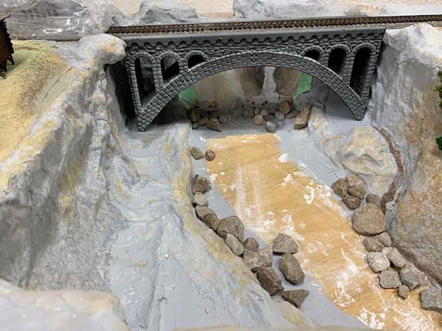
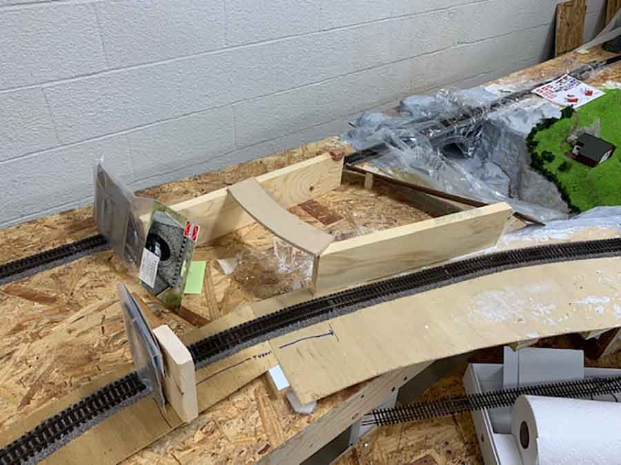
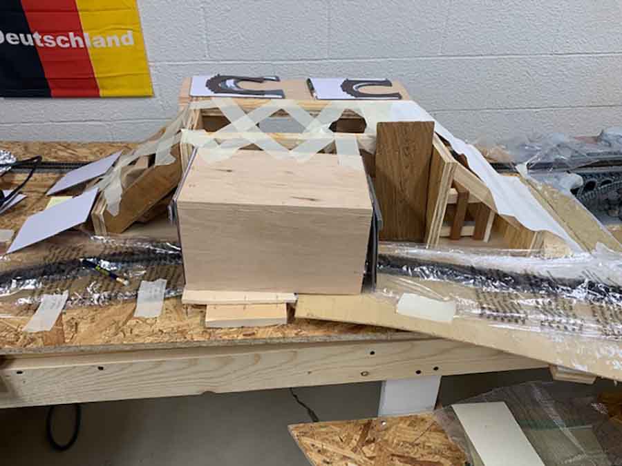
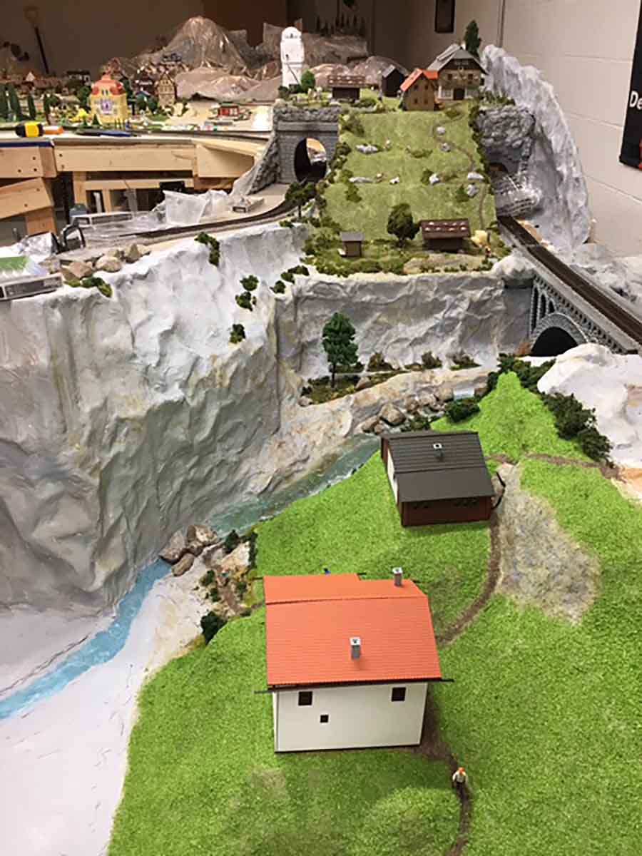
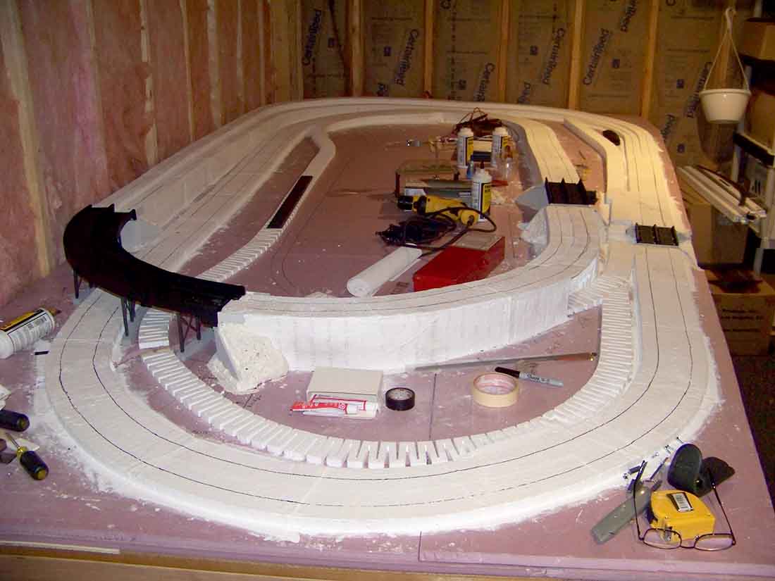
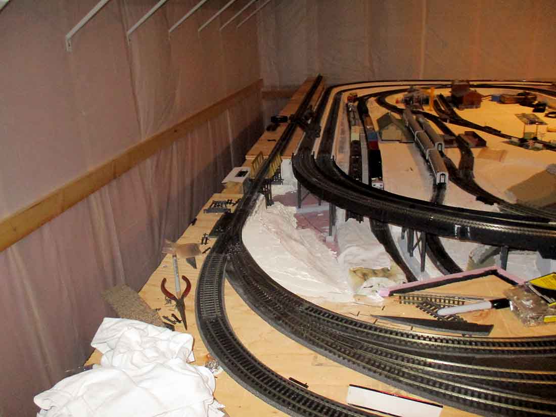
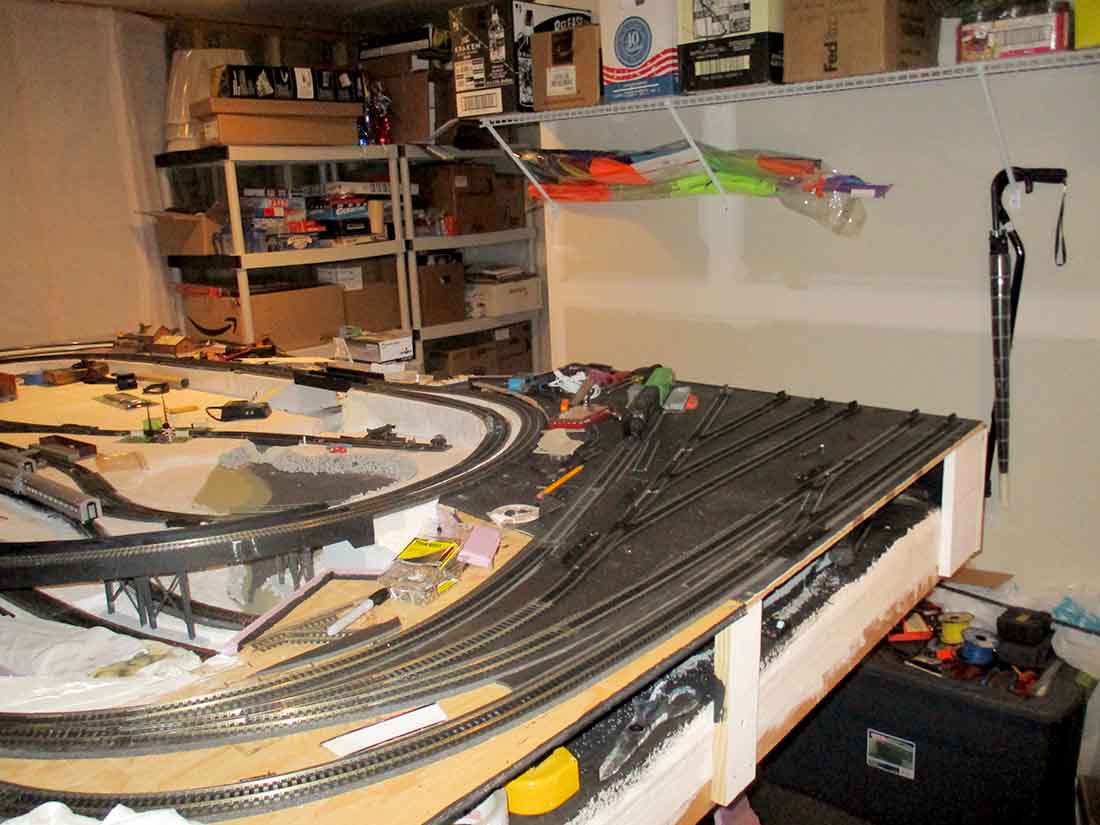
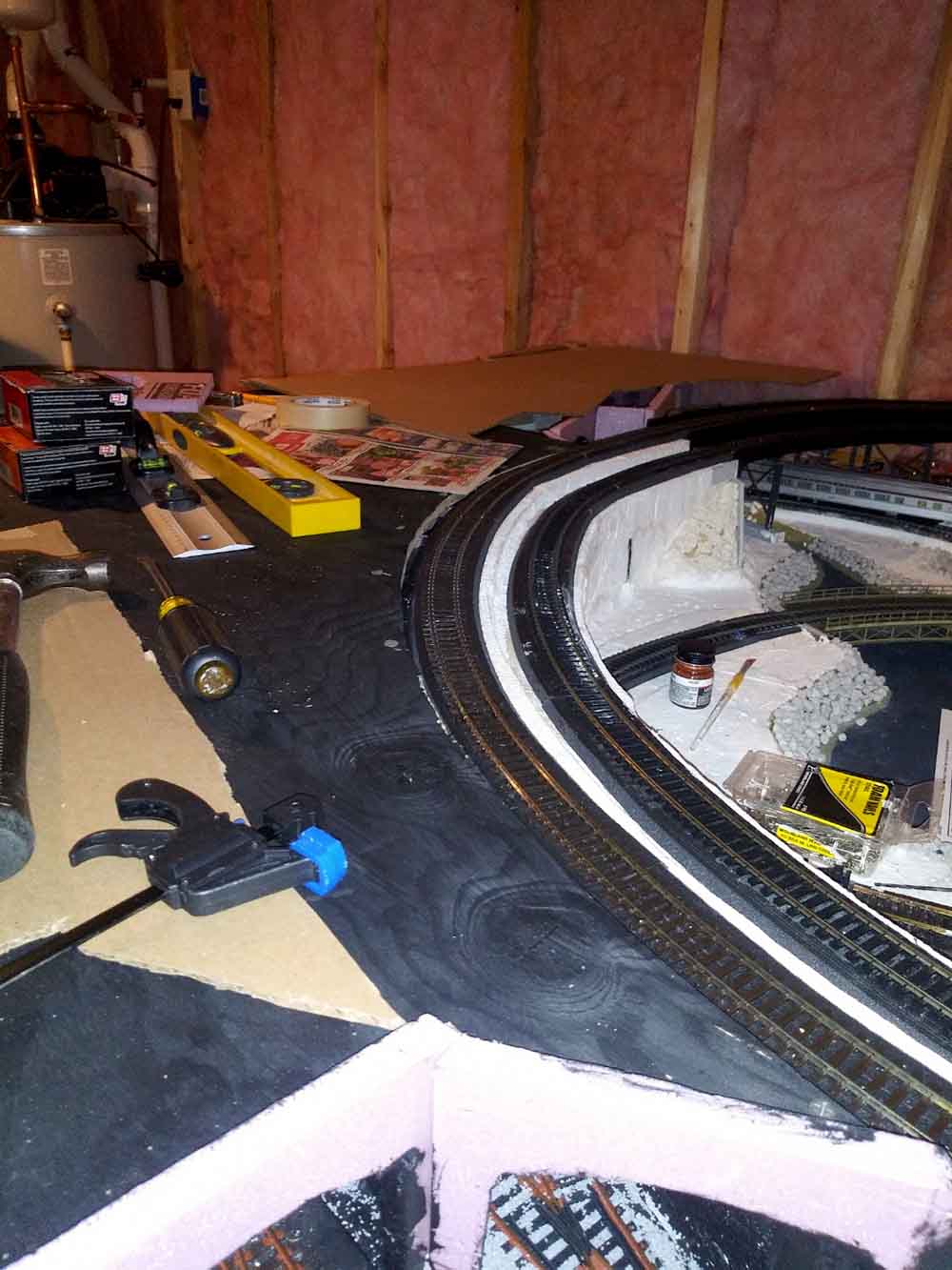
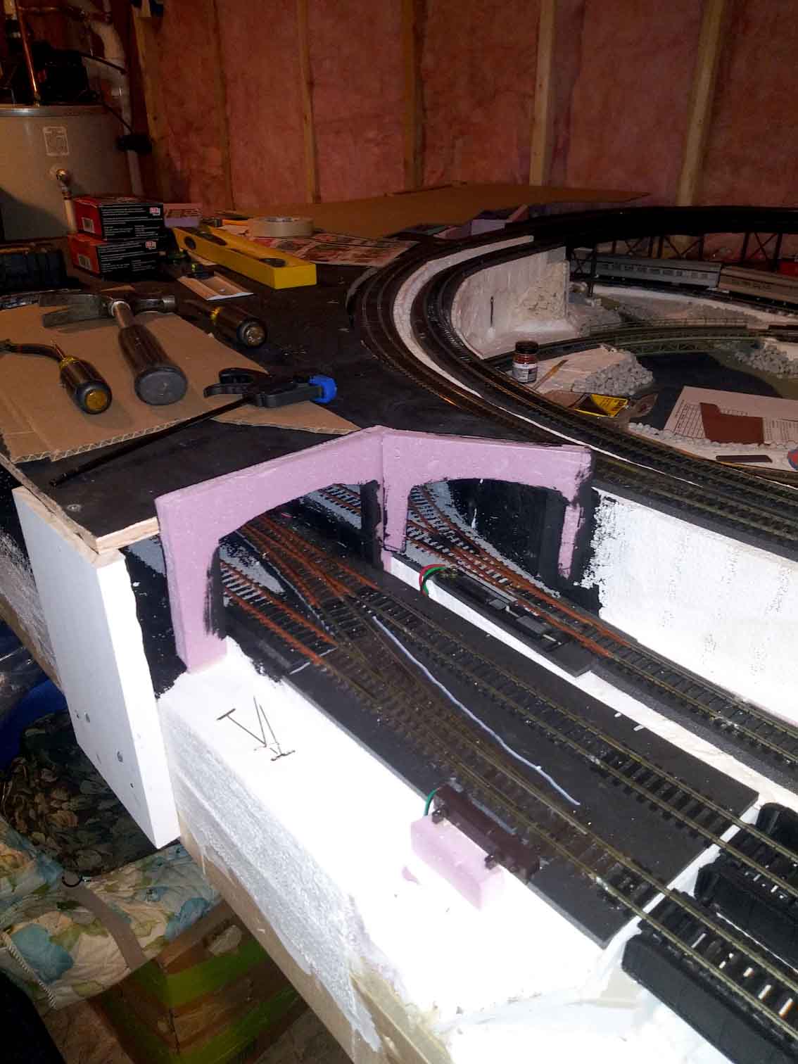
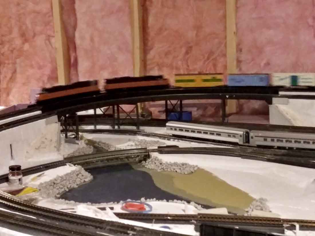
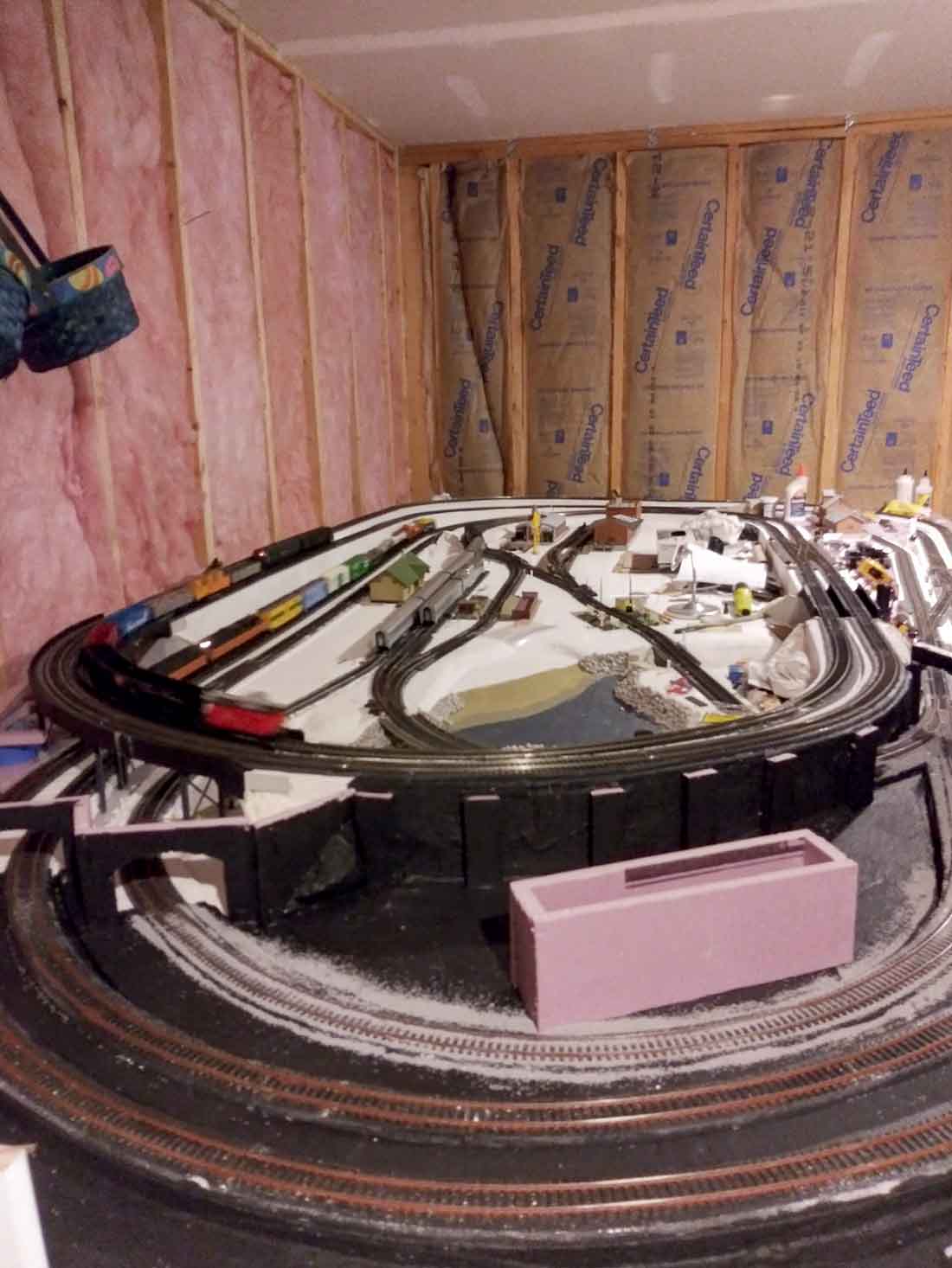
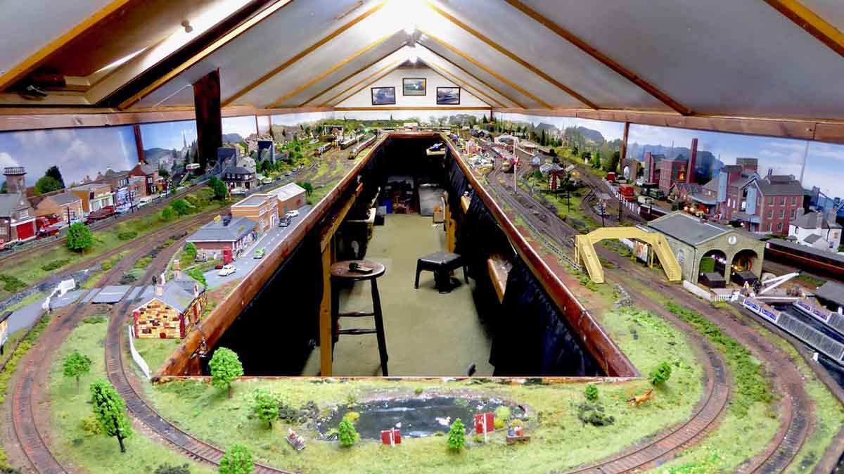
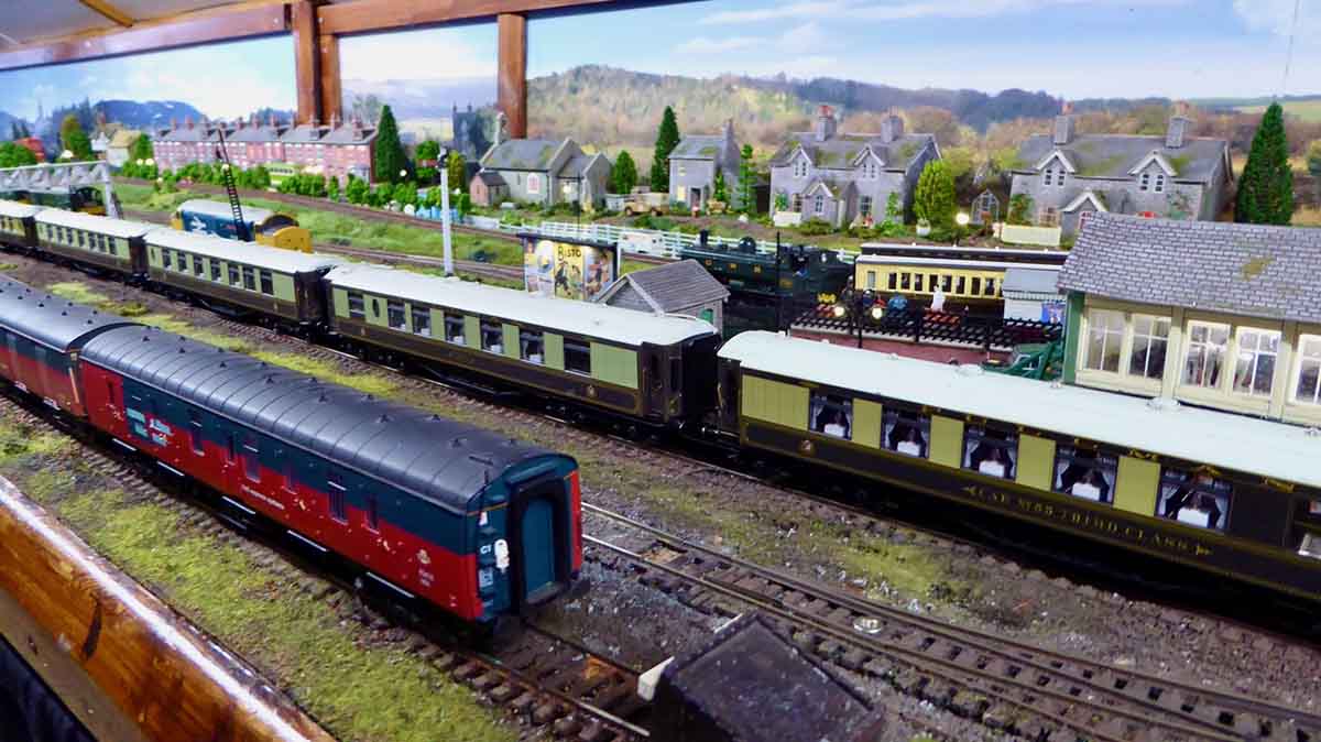
Just uploaded this video showing what changes have been done so far.
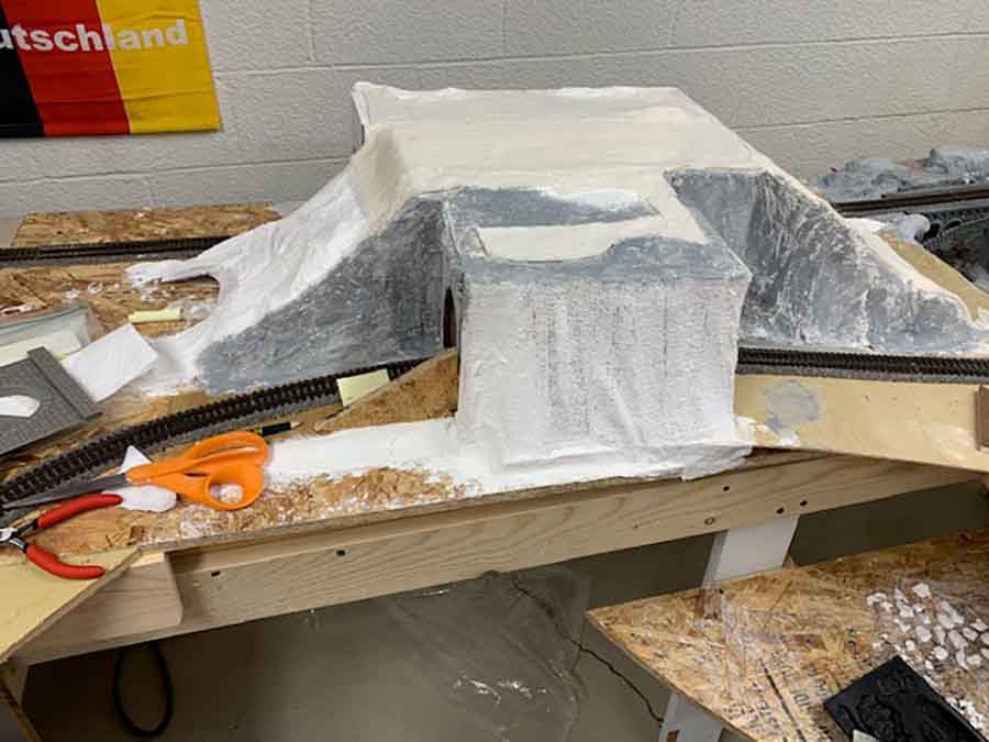
Mainly showing the incline now added and the plaster cloth added, a test run going both forward and reverse over it, and well all I can say is well chuffed, it runs so smooth now ….
The downside is I am not sure when I shall be able to complete it all, I had a bit of a fall in the garden Saturday, more a trip up on a step, but did something to my knee.
It could be some time before I can continue and send more videos.
Regards
Dave”
Poor old Dangerous Dave. I hope he gets well soon.
When it comes to inclines, I’m always reminded of Bruces’s incline post.
Now on to Marvin:
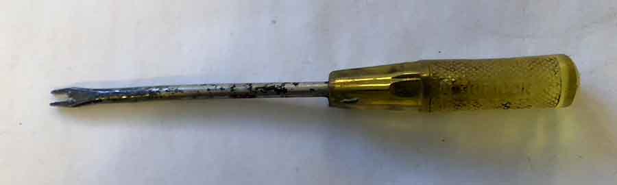
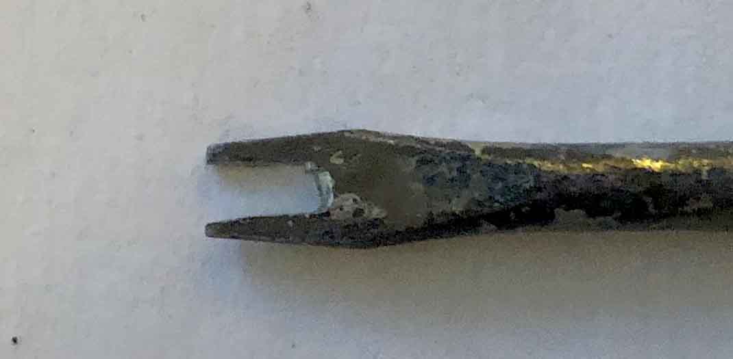
“Al, attached is a photo of logs from an upper Midwest weed called “Common Mullen”. Besides log cars, a 7 footer makes a great walking stick.
Marvin”
Now to Jeff:
” Hi Al
I took my layout down last week for cleaning purposes. Putting it back up is like a jigsaw puzzle. I am suggesting seeing my layo0/uts are basically one dinemsional and I have space for a 8.5 (9×9) x 8.5 ft equivalent. If i did not have furniture in my living it could be as big as 12×12 and still able to walk about it.
For any novice, veteran, expert I pass along these tidbits having toiled in the ho scale for forty six years now.
Some common sense items: strip outlets with surge protection. Alot of people do not realize how much power juice a non battery operated train set takes to run and use. A lot of fires could start of be prevented by not using these.
Common safety tools: Safety glasses and needle nose pliers I find invaluable when it comes to handingly the track joiners….If at all possible have one of the rolling magnets handy you will not believe what they pick up.
When it says age seven and up, make sure adult supervision is a must. Anything under seven, there are too many parts pieces for infants to young children to get hurt cut or even swallow pieces of trains.
If you find this useful thank you and please pass along to your readers. If you would like pictures of my newest endeavor with my trains ill pass them along.
Thanks for now.
Jeff”
And lastly Larry has a question:
“Hi Al,
I’ve enjoyed all of your pictures and articles. Like many I’m no spring rooster and decided to get back into the hobby.
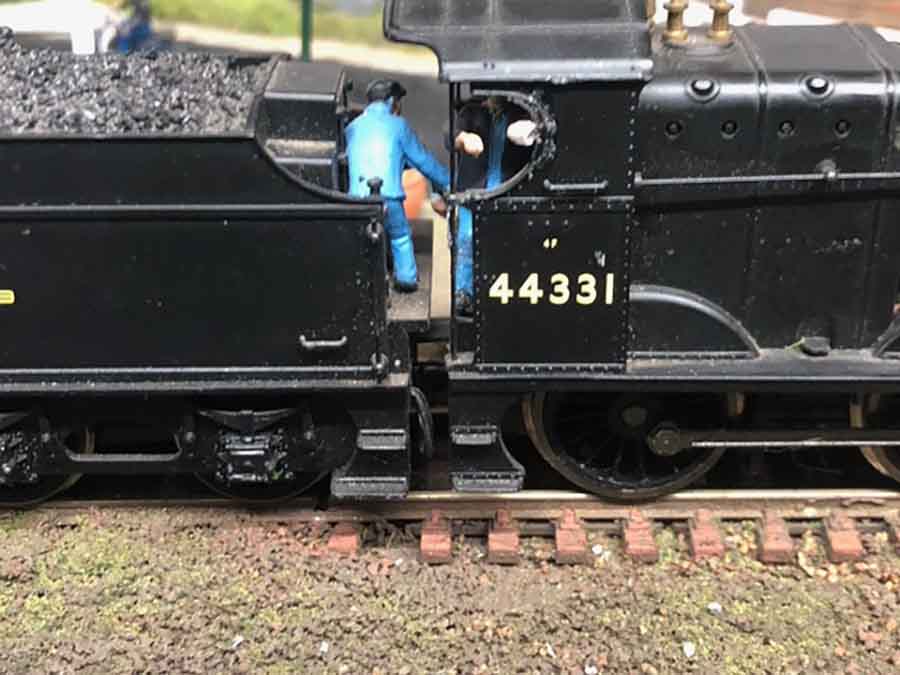
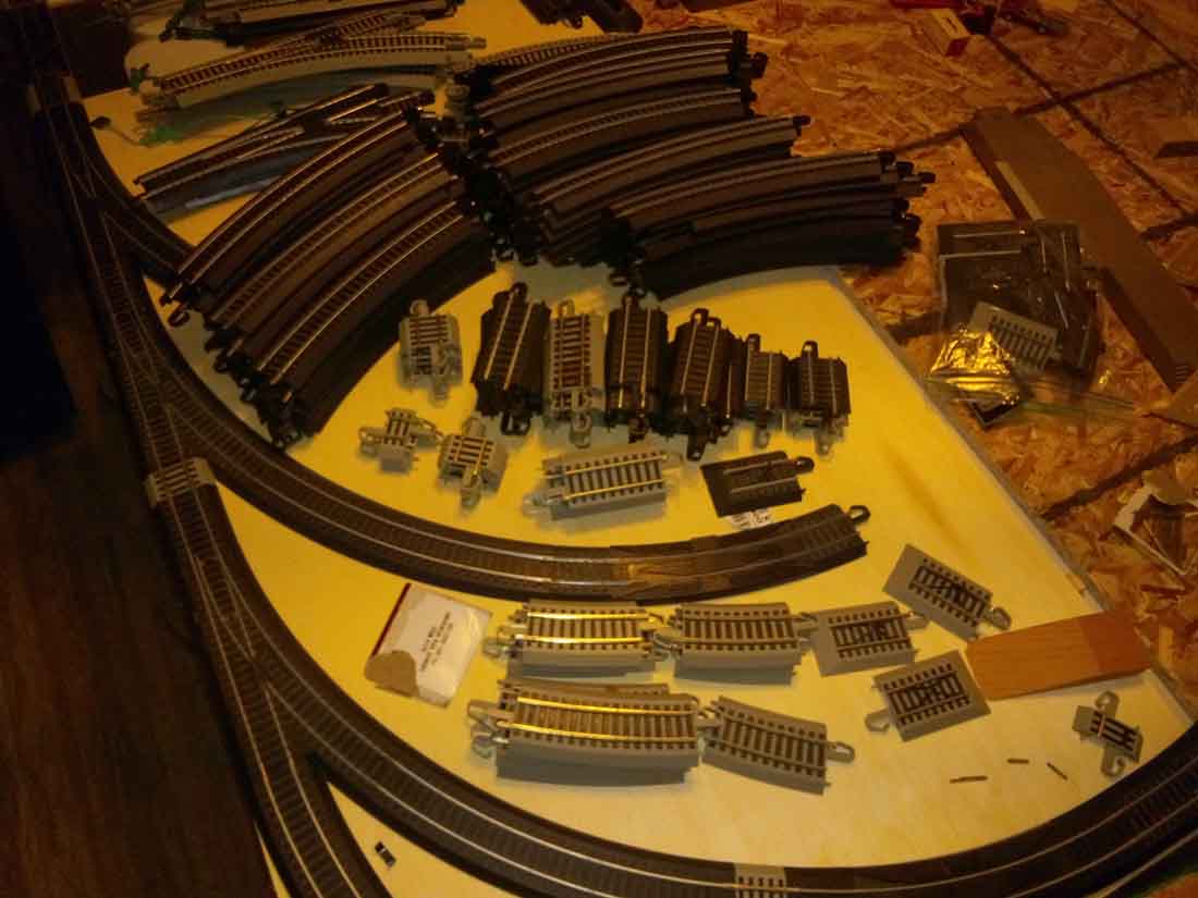
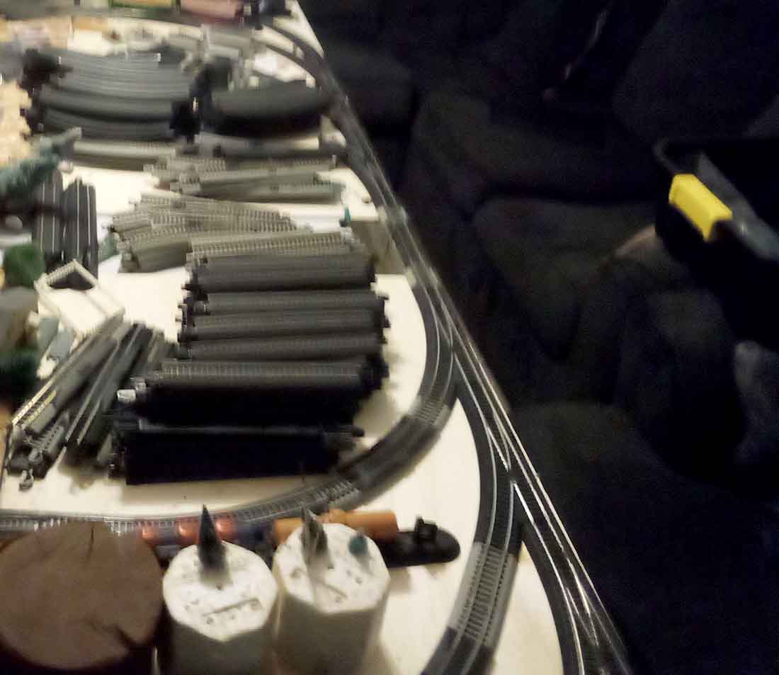
The question is that I have brass tracks and I would like to know how to keep them clean? In so many of the pictures the track looks like brass unless that’s just how they look in the pictures.
Can you guys give me any advise.
Thanks,
Larry”
Over the years, there have been many, many posts on track cleaning.
For me, the one that sticks out the most is Kim’s track cleaner.
A big thanks to Ben for sharing his model train large trees, and to Larry, Jeff, Marvin and Dave.
That’s all for today folks.
Please do keep ’em coming.
And if today is the day you join in on the fun and start your layout, the Beginner’s Guide is here.
Best
Al
PS Latest ebay cheat sheet is here.