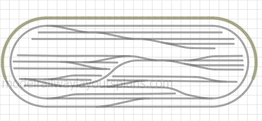
There’s quite a few HO shelf layouts on the blog now. Here’s Roberts:
“Hello Al,
First off I want to let you know how overwhelmed I was at the response to my layout.
My children and grandchildren think my ‘toy’ trains are pretty but having a group of real model train guys let me know that they think my layout is pretty good really made my day and my week and probably my year as well.
Thanks to all for you comments and suggestions.
Secondly, it’s funny how one always needs more room for a layout.
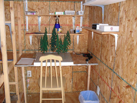
I decided to expand my layout by using my 12 x 12 storage shed in the back yard. I added insulation, OSB walls, ran electric and added an a/c/ unit through the wall.
I use a little electric heater in the winter.
I decided I liked HO shelf layouts with a duck under at about 54” so I didn’t have to crawl. My train room also included a small space to work.
I also wanted to use as much as possible from my 1st layout.
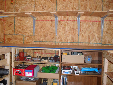
On my first layout I used a plywood sheet covered with pink foam insulation.
The track was glued down (with white glue). On this layout I used an OSB base covered with sound board and the track was tacked with track nails. Some new things I tried:
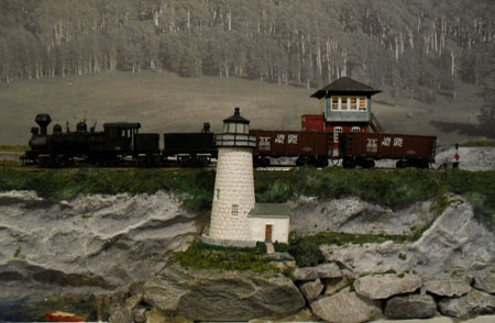
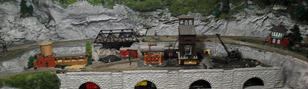
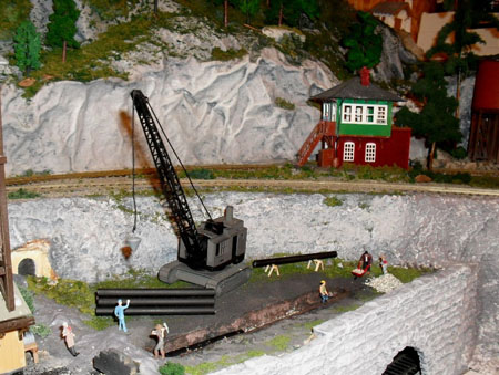
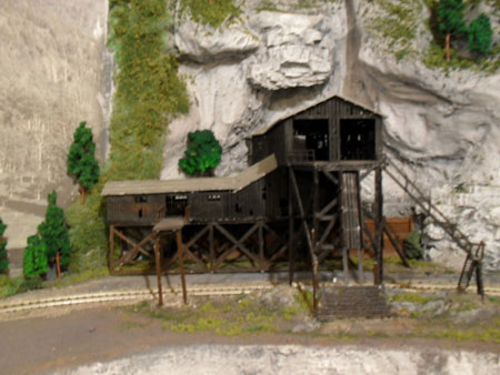
1. I tried my hand at scratch building some items.
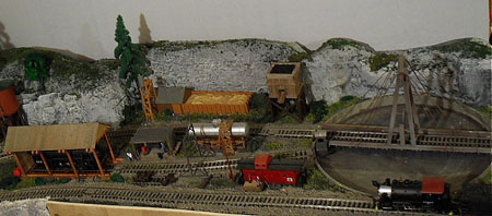
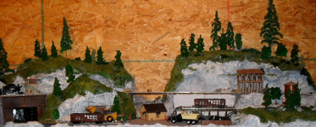
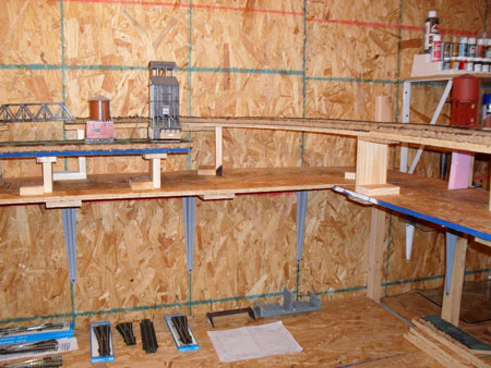
2. Built using different levels to add interest.
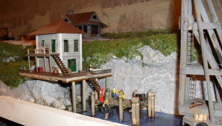
3. Added a water feature. Didn’t do too good on the waves part.
4. Built my scenery with screen, cardboard strips, balled-up newspaper and foam all covered with plaster cloth or plaster or drywall compound or tinfoil. I wanted to experiment to test what worked best for me.
5. Built some trees with kits(didn’t work out too well) and also weeds painted green.
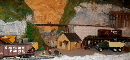
6. Got some latex and built some molds …. A fun project. Also bought some rubber rock molds as well.
7. Added people into my vignettes. My wife’s idea. She was right, they really make the scene come alive.
8. Used a turntable with an auto reverser and a switch to run the turntable backwards and forwards. Figured out later that I could have used a switch instead of the Auto Reverser and saved a lot of money.
A couple of things I learned on the way:
1. Never put your turnouts at the beginning or end of a curve. Always start them on a straight piece of track. They always caused a derailment.
2. Duckunders are the easiest. I first tried a lift out… kind of a pain with the off and on thing and my alignment always needed a little adjustment. Then I got cute and built an elevator thing using a car antenna hung from the ceiling and the bridge riding between two metal tracks. The next try was a lift-up thing mounted on a furniture hinge. Too bad I didn’t take some pictures of these failures on my part. Most were good for a few laughs.
3. I really don’t like working with a magnifier mounted on my head and besides, my hands shake at the most inopportune times. Can’t imagine how anybody works with N or Z scale. I stand in awe of these folks.
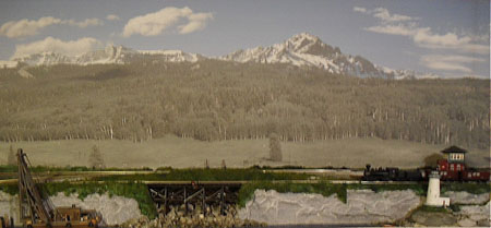
4. Always add the background (if desired) before you build the layout.
I added many more little vignettes to this layout but I don’t have pictures because at this point I decided to get out of HO and go into something bigger. I decided on On30 which is O scale with the train’s running on HO track.
This began another journey …FYI, I was now 68 at this time.
Bob”
Now on to Kevin:
“Hi Alastair
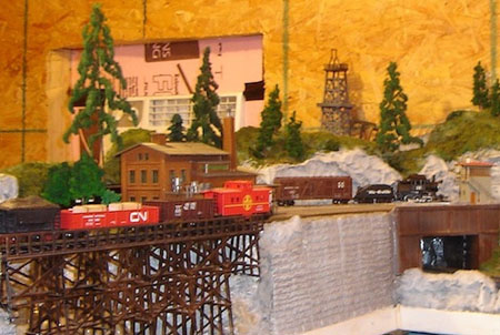
Here is some new pictures of my new viaduct scene.
I’ve used static grass,seafoam trees and Heki flor to recreate flock.The viaduct is scratch built using emboss plastikard and greenscene plastic strips.
The river is Woodland scenic realistic water and realistic water effects and dry brushed white paint.
Kevin”


A huge thanks to Rob – it’s easy to see how HO Shelf layouts are easy to find space for.
That’s all for today folks.
Please do keep ’em coming.
And if you want to your start, on your very own layout, the Beginner’s Guide is here.
Best
Al
PS Latest ebay cheat sheet is here.

")