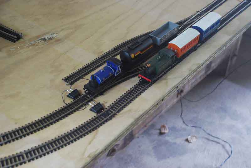
Lawrence has been in touch because of his model train incline.
Like many of us, he found out the hard way what is acceptable when it comes to running trains up an incline.
“Hi Al
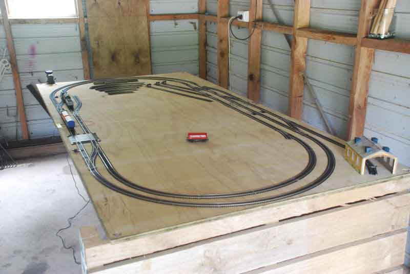
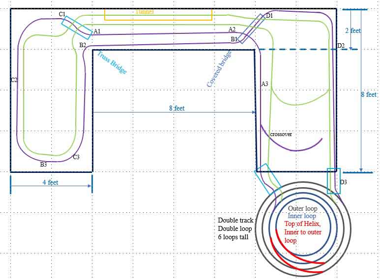
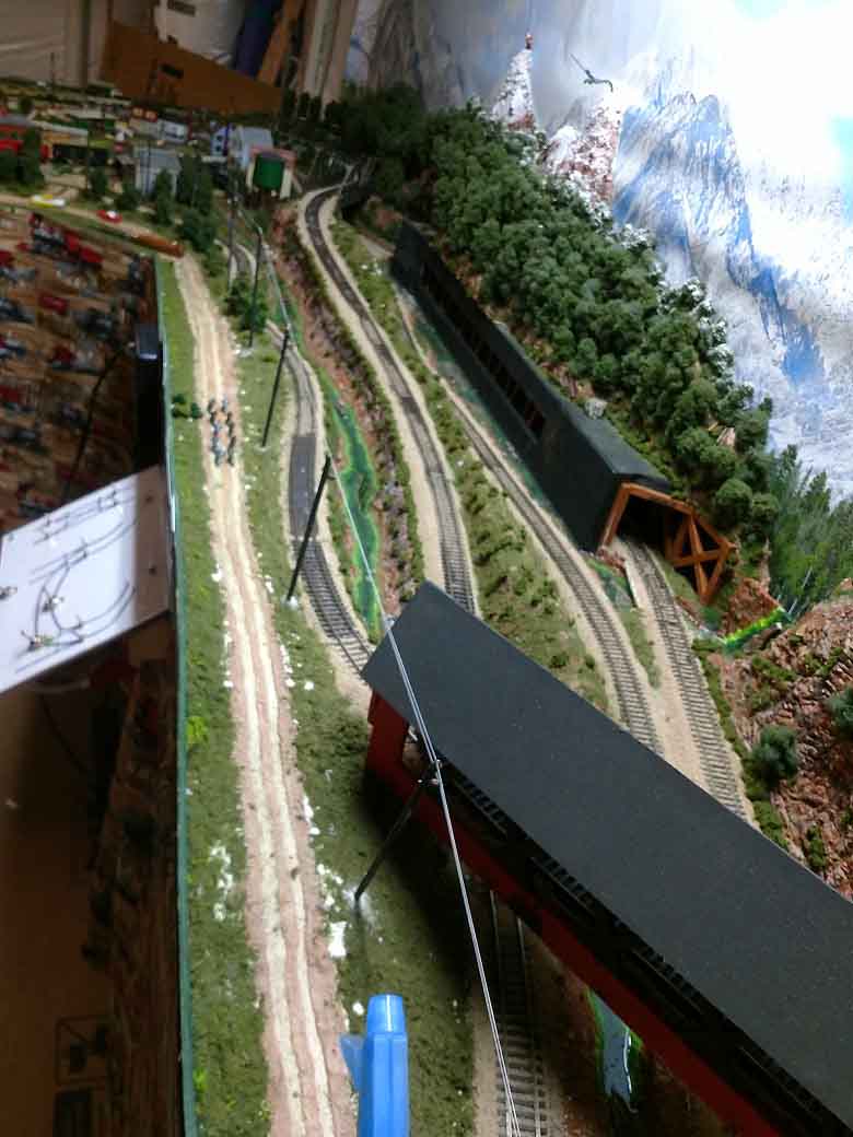
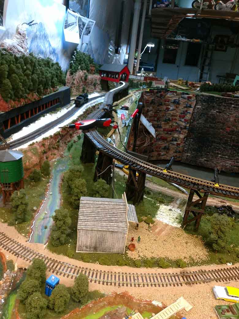
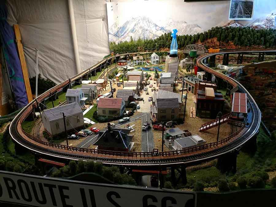
The following pictures are all referenced to the first picture that displays the layout that I have.
When I initially built the layout, I did not know what I was doing when it came to inclines. Since then I found the formula for determining the percent of grade.
I was having trouble with trains going uphill and using the formula I found out that I made grades from 3.5% to 5.5%. The optimum is 2%. My model train incline was too steep.
Example A1 to A2 was 5.5%, to make it 2% I had to change the rise from A1 to A3 (on the diagram). The A1-A2 track goes from the top to under the covered bridge. The B1-B2 track, at 3.9% goes from the covered bridge.
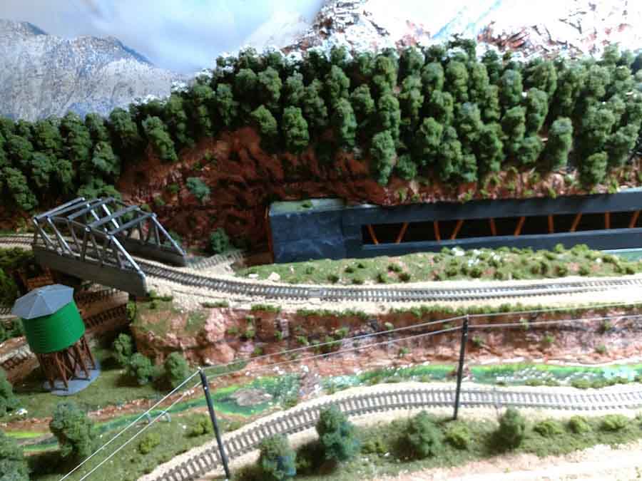
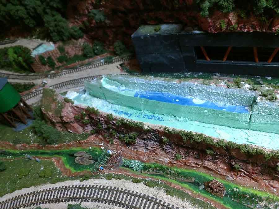
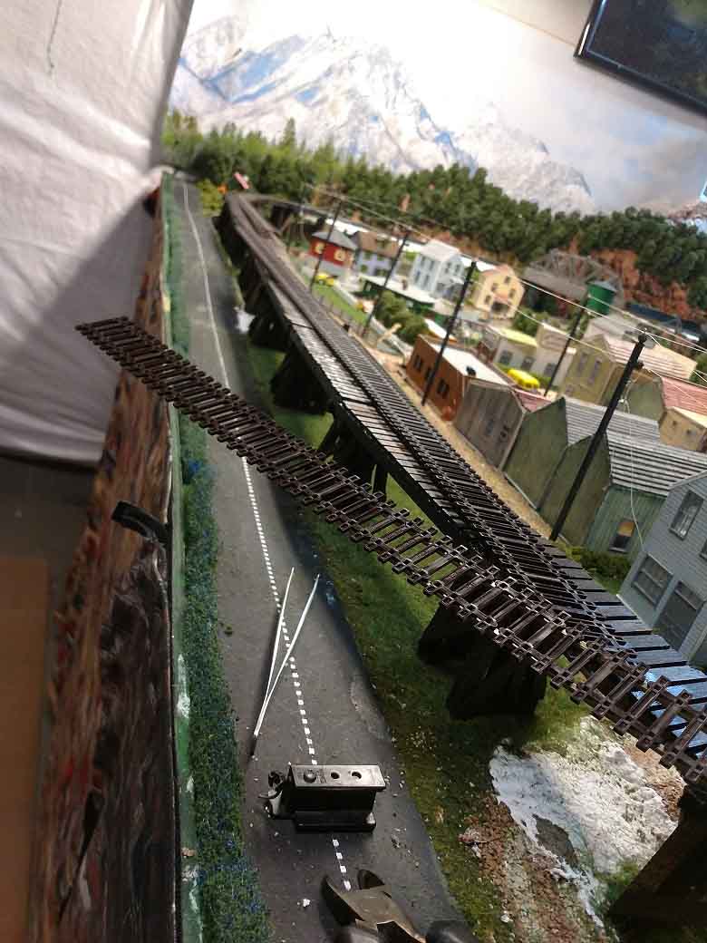
Another angle of the two mentioned tracks before reconstruction. I wanted to pull the track without having to redo all the scenery. Lifting the covered bridge off the layout and starting to remove the track to the base foam layer at the lower end (A2 area).
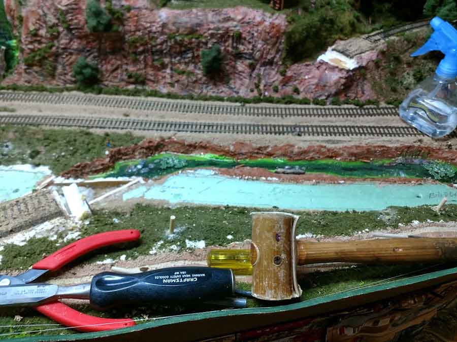
Cutting out the track at the upper end, cutting down to the base foam but keeping the scenery intact as much as possible on either side. Another shot of the A1 section of the track area cut out. the smaller bridge also had to be temp taken out.
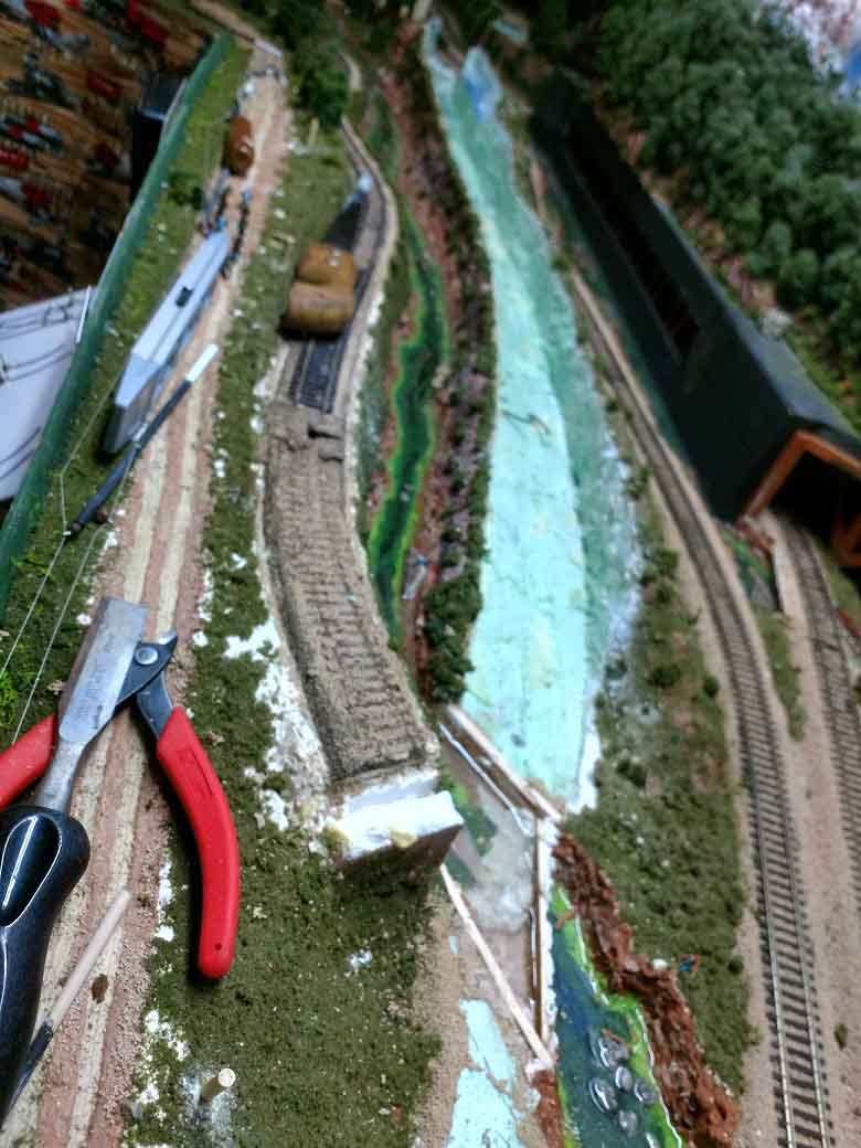
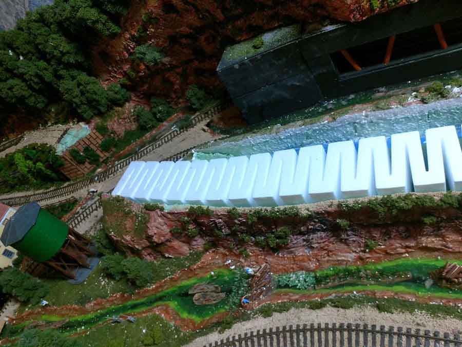
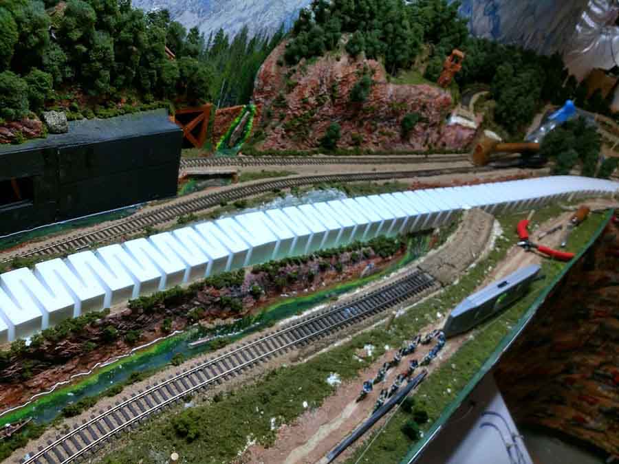
The upper end of the A1 section with the store bought 2% grade foam in place. The middle section of the 2% foam in place. this is where I found out at the level of the track under the covered bridge would be 2 inches higher than before. This is a problem as before the change there was only one quarter of an inch clearance for the train to travel under the bridge. Laying the 2% foam around to the now A3 location after puling all the track to this point. The D section of track was handled in the same way. BUT – –
Forcing the B1 section to now be raised from 3 inches to 5 inches the B3 section goes around to the new B3 area. BUT – – The C1-C2 section over lapped the B3 section. PLUS, at the B3-C3 area two roads cross the bridge.
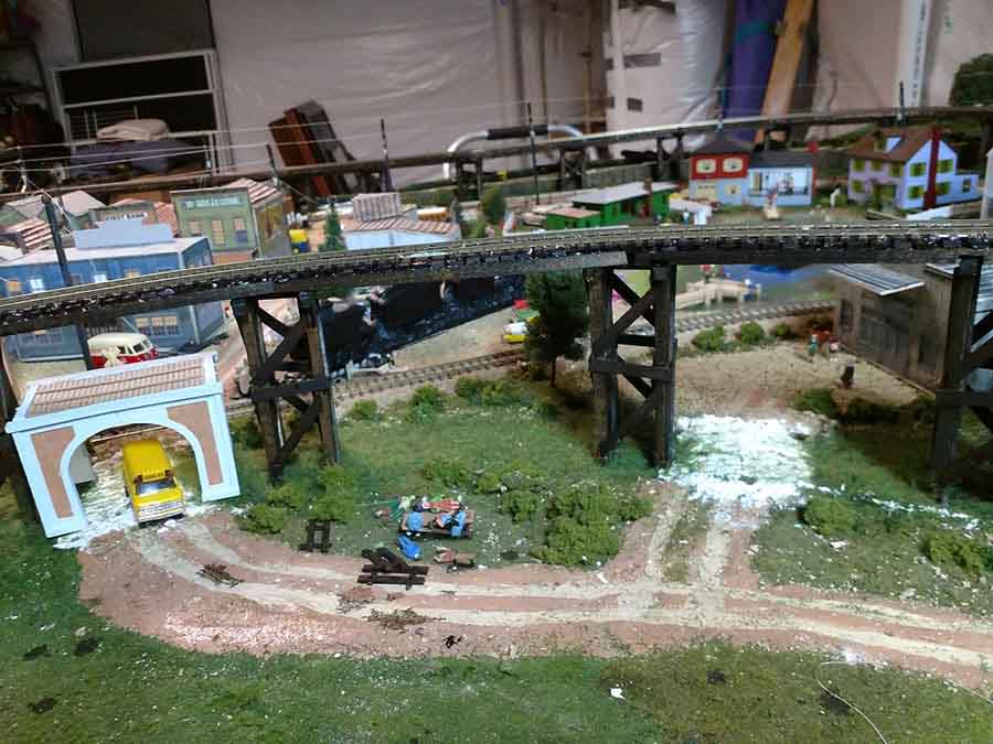
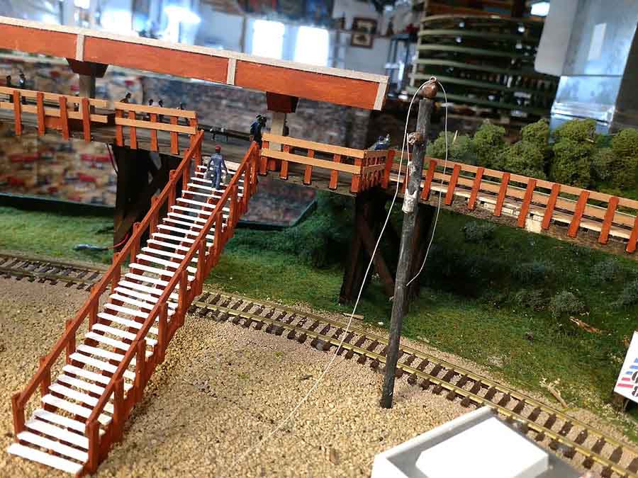
To solve the problem a Trestle bridge had to be built from B1 all the way around to C1. Here the bridge goes over the road (under construction) to the Antique shop.
The B section of the Trestle, in the foreground, and the C section to the rear. N gauge train tunnels built for the HO gauge layout for auto traffic.The train is on the mostly finished A section of track.
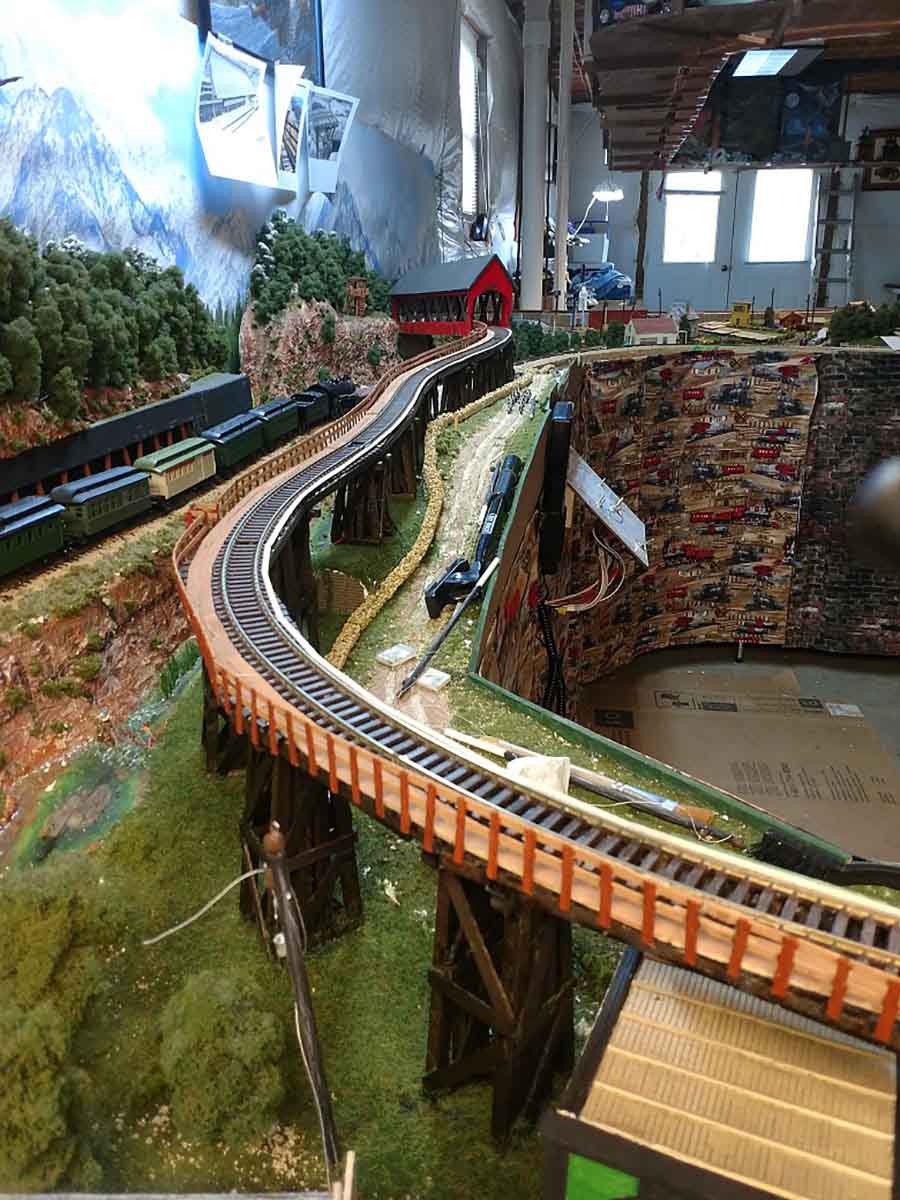
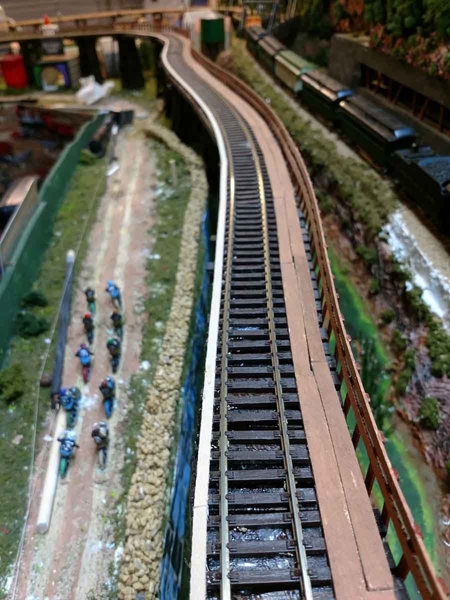
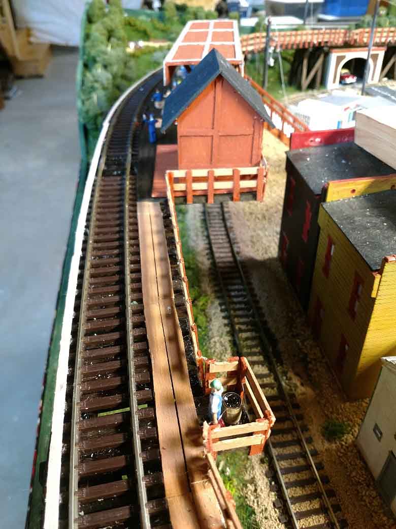
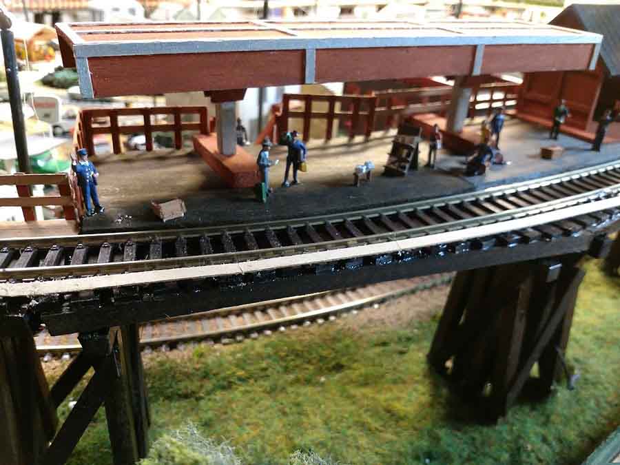
The trestle has a walkway for the engineers and a banister for safety. Another pic of the A1 section of trestle track finished. About where the A2 area was a new raised train waiting station for passengers.Another angle of the passenger station. Also, the water barrel in place for the steam engine usage. The passenger station and news stand.
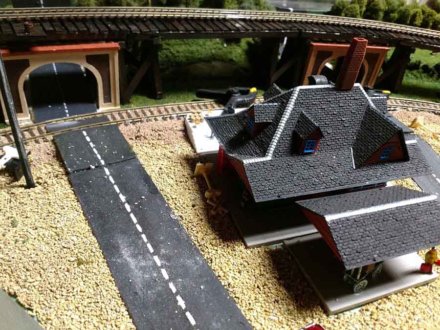
The two roads going under the trestle bridge with the N gauge tunnels. The trestle had to be raised not the 1-inch minimum need for the 2% grade in both directions but another inch to allow for the auto tunnels. Laying the track around the C section. The actual last to be worked on at this time.
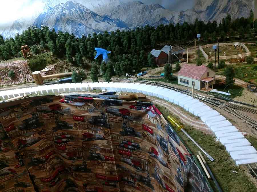
And last off is a pic of the overall area for the trestle bridge – it shows the my model train incline – from the upper right, around the town, to the middle back. The banister still not finished in the C section. That is physically 20 feet of layout trestle track.
Lawrence”
Model train incline:
A huge thanks to Lawrence for putting this together. Just goes to show a model train incline is no different to any other part of scenery – one small change to your track means lots of other changes need to happen too…
That’s all for today folks – but please don’t forget the Beginner’s Guide if you want to get going on your own layout and side step the mistakes we all make.
Keep ’em coming.
Best
Al
PS Latest ebay cheat sheet here.
PPS And if you fancy reading even more on inclines, this post will help.
PPPS Here’s another great incline ‘how to’ as well.