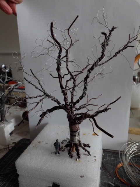
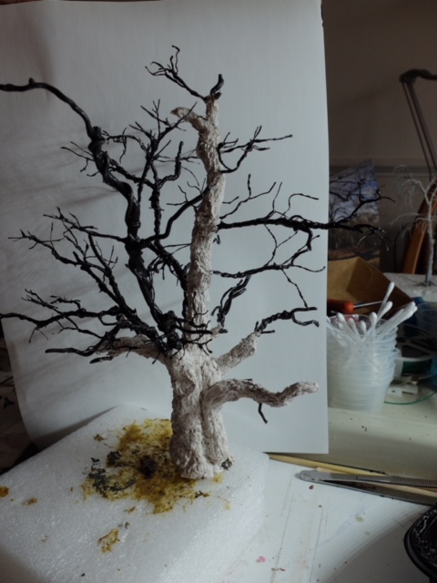
Fred’s been in touch with a fantastic ‘how to’ on making model railroad trees.
He’s a man of few words, but his pics speak for him.
There are lots of tree ‘how to’ posts on the site, but this one really is spectacular.
“Hi I must say some cracking tips of late ….love them ..
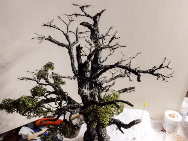
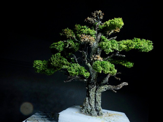
Thought this might be of interest to some my take on a wire tree
Fred”
Fred’s also made a ‘Making model railroad trees’ youtube:
Fred’s post reminded me of Rob’s on trees too:
How to make model train trees.
In fact, there’s lots on making model railroad trees, on the blog. Here’s a few more:
Trees for a model train layout.
Now on to Michael who has been in touch again.
“Al,
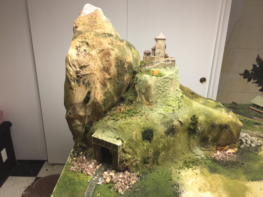
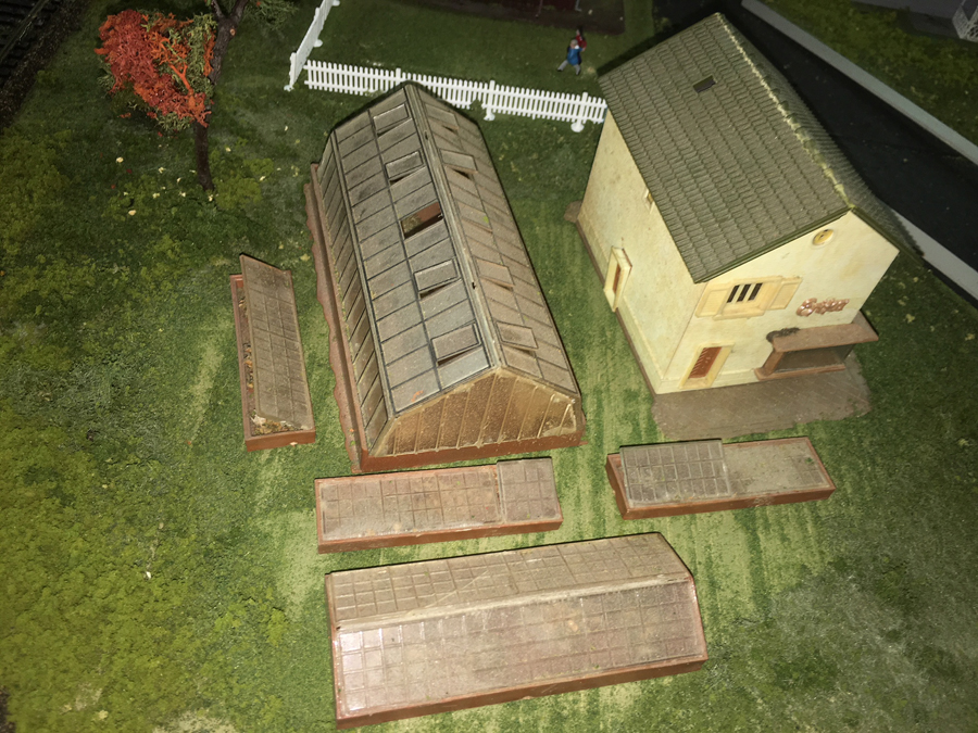
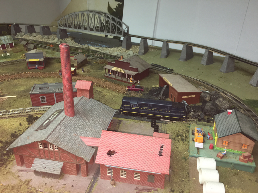
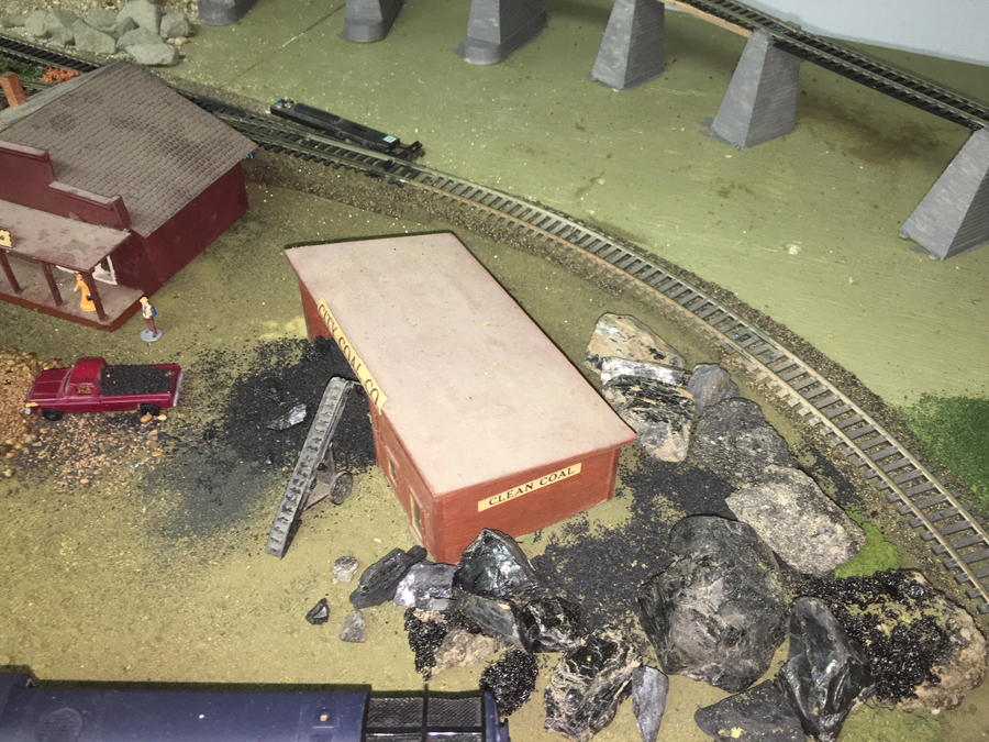
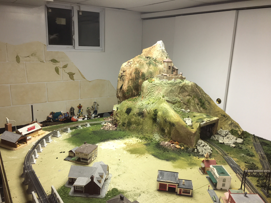
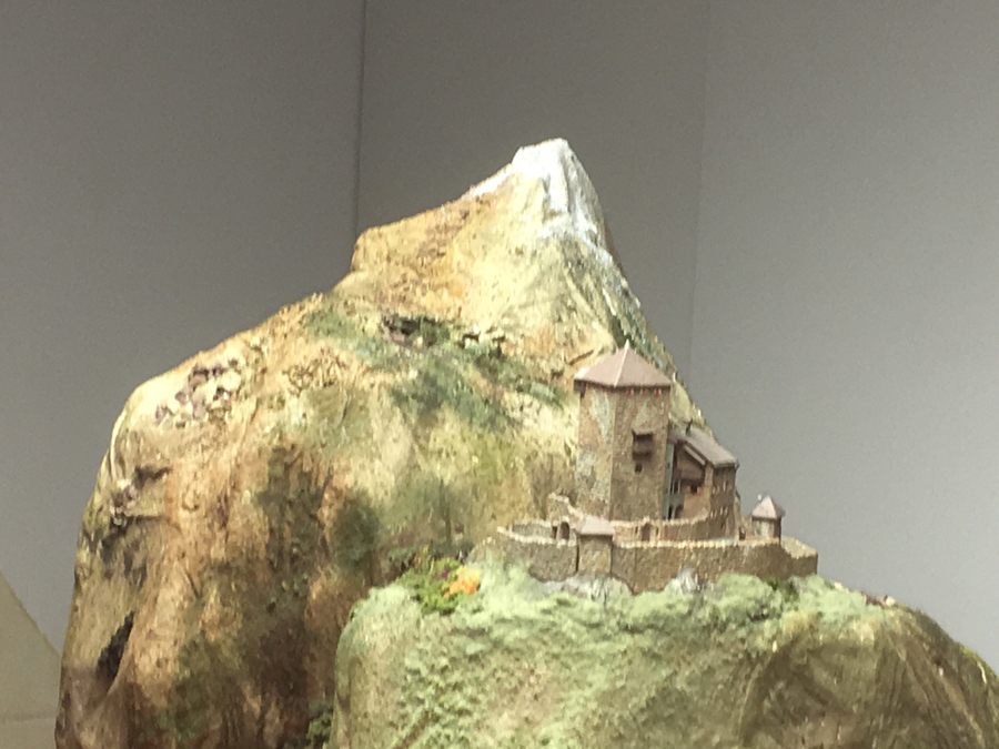
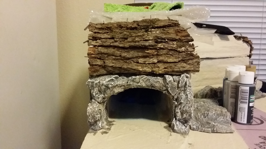
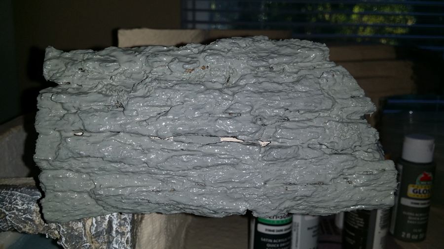
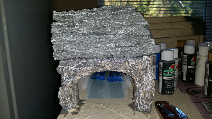
Here are a few pictures of my tunnel entrances, before and after assembly and the natural materials used.
I used tree bark from a white oak tree in the woods that I found and glued them (all 4 pcs.) to the top of the tunnel entrances, let them dry and painted them with a dark gray mixed with white paint and water.
Then dry brushed them with white paint.
Mickael”
“I have been reading this article for some time now and enjoy it very much. Unlike most on here, I run both O and S scale trains.
I thought I would share so hints I got from the old timers. Since I am 70 maybe I am the old timer now. I use a lot of wheat and rice bulbs with bare wire leads. I found nail polish make a good wire insulation after all connections are made. I also use it to lock on nuts to bolts and numerous other things. I prefer red so I can tell that everything is covered, but clear , black or any color will do.
The other hint is artificial coal. The original artificial coal was made from Bakelite which has some hazard properties. They then went to plastic which also has its draw backs. I found these lodged in motors and cut up belts using coal loaders. I also found black aquarium gravel worked better but still jammed up belts and was work to un-lodge from places. Try Grape Nuts cereal. Dry in microwave for 30 seconds then spray paint black. It takes a few spray times. Now if this gets caught in the motor or belts is crunches up and does not lodge as often as other materials. It takes just a little air and a brush to clean up Also safer for children and pets.
Your comments please….
Joseph”
“Well, seeing as how I am the least handy person on this planet, and cheap to boot, here are a couple:
Since my layout is in a permanent winter mode, I wrapped the plywood bases in white bedsheets —
It makes a a great “canvas” for laying down landscaping and a SUPERB conduit to run the wiring between the sheets and the wood – no drilling required.
The “snow” is actually a ceramic product: Duncan’s no-fire snow, available, among others, online at Amazon. You can paint or sculpt it on, and it dries to a plaster-like state.
More recently I wanted to add some ice-covered ponds, and as I dislike mixing chemicals, etc. for water effects, I went to the nearest drugstore and purchased a couple of ladies’ hand mirrors, you know, the kind they carry in their purses. I laid down some snow and partially buried them, feathering the edges with more snow.
But then I wanted a larger ice-covered swamp or pond, and here comes the cheapest solution of all: I headed to the kitchen, ripped off a good-sized sheet of food clingwrap (like Saran Wrap), painted the bedsheet in the colors I wanted to show through, and laid the wrap on top with a little landscape cement. You can make it smooth or rippled, and it looks great!
I hope these help.
Bill”
A huge thanks to Fred for his fab ‘how to’ on making model railroad trees, and to Mickael and Bill.
It just goes to show (again) that you should never throw anything out, and with a bit of thought and creativity, you can get stunning results.
That’s all for today, folks.
Please do keep ’em coming.
And if you want to take that first step with your very own layout, the Beginner’s Guide is here.
Best
Al