Bill’s been in touch with some vintage model railroad pics.
Well, perhaps not too vintage but it’s amazing how black and white pics add to a theme:
“Hi Al
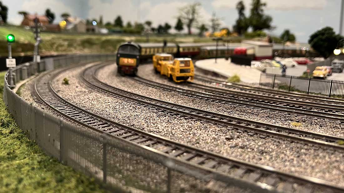
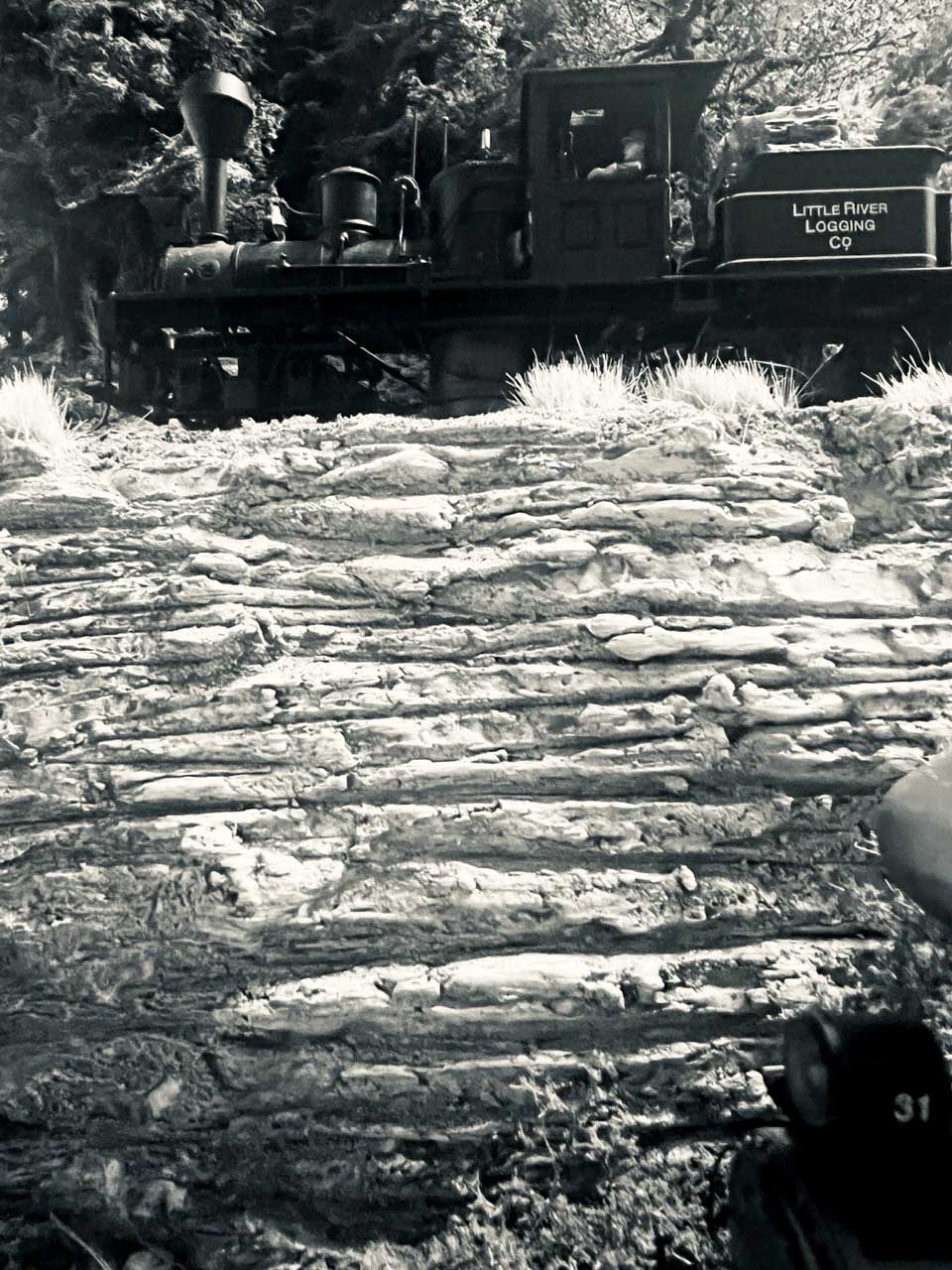
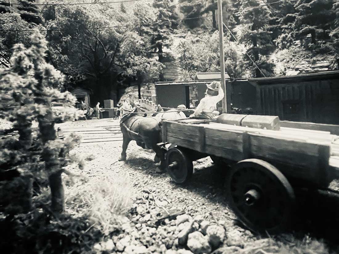
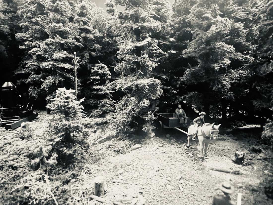
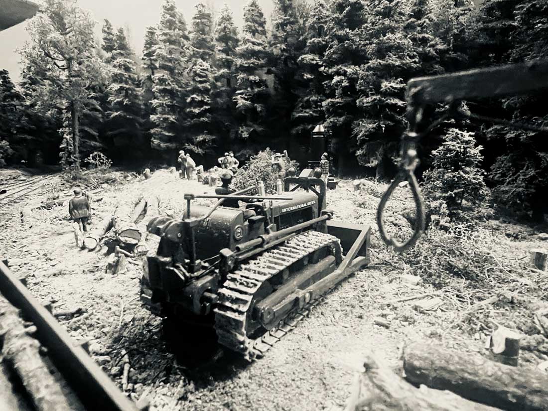
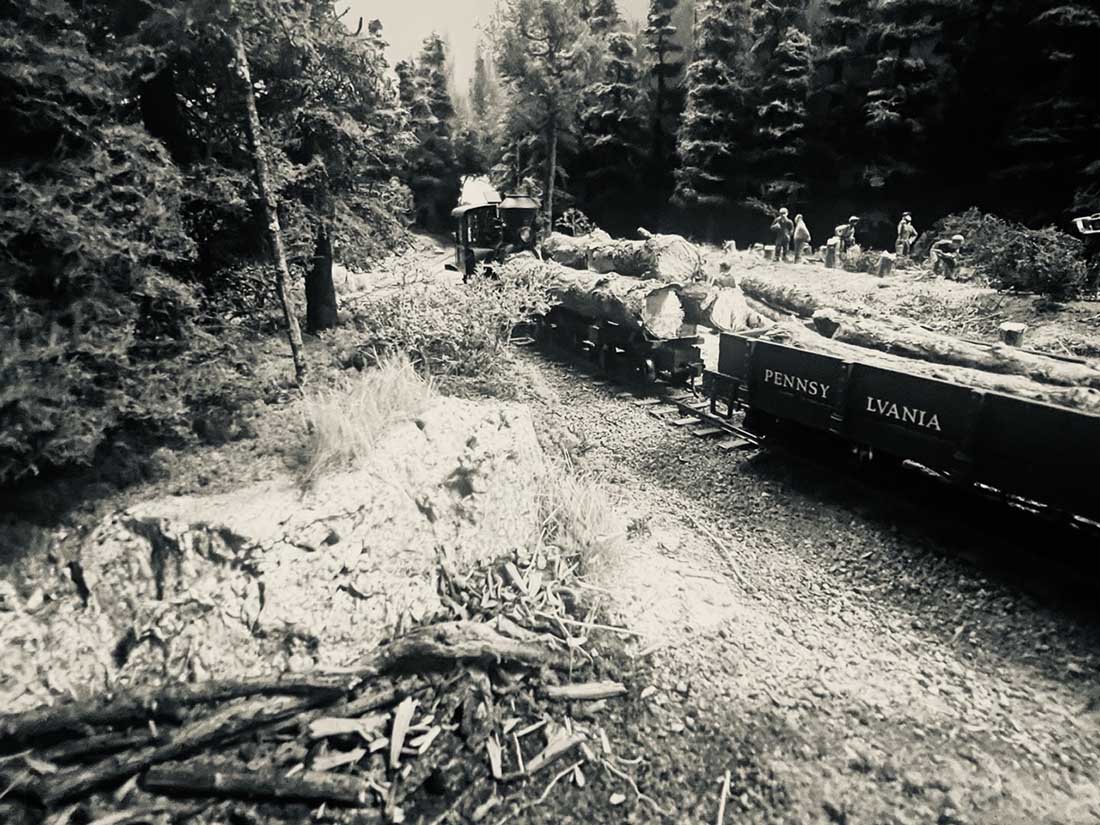
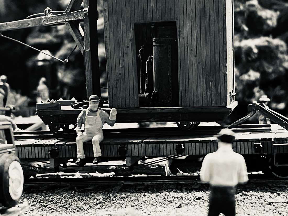
Hope this finds you well. I had a friend make a comment about scenes on my O Scale layout wondering how scenes would look if captured in black and white.
His question was if in black and white, could you tell they are models?
I thought it an interesting question so I took a number of photographs on my iPhone and went into the photo edit function and change them to black and white.
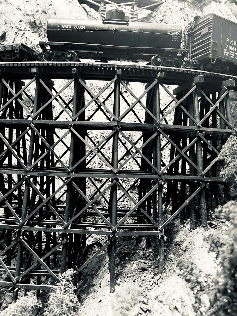
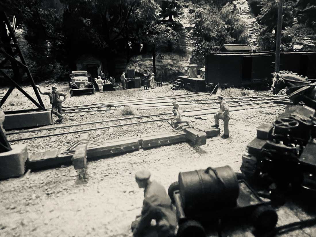
Certainly some look like models still but there are some that really look like a scene from long ago.
It was fun and I thought I’d share the end results.
Best
Bill”
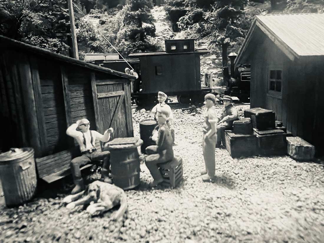
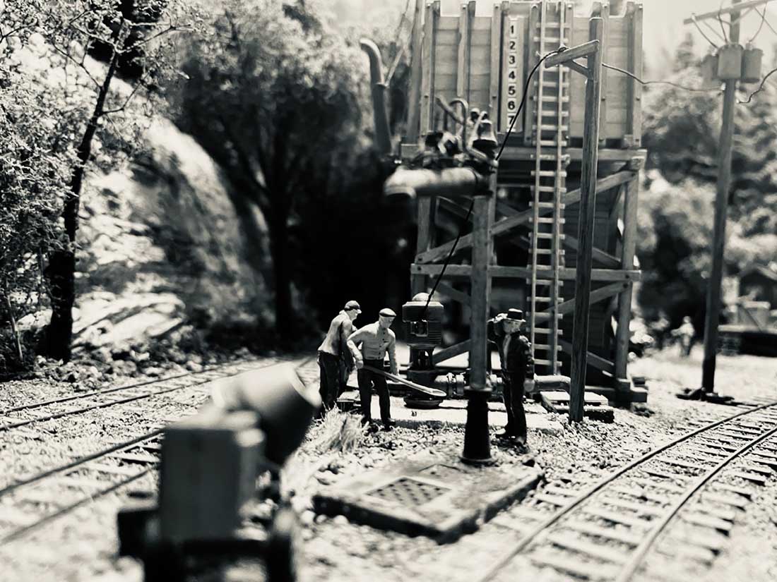
A huge big thanks to Bill – it’s amazing how much a black and white pic adds to the nostalgia.
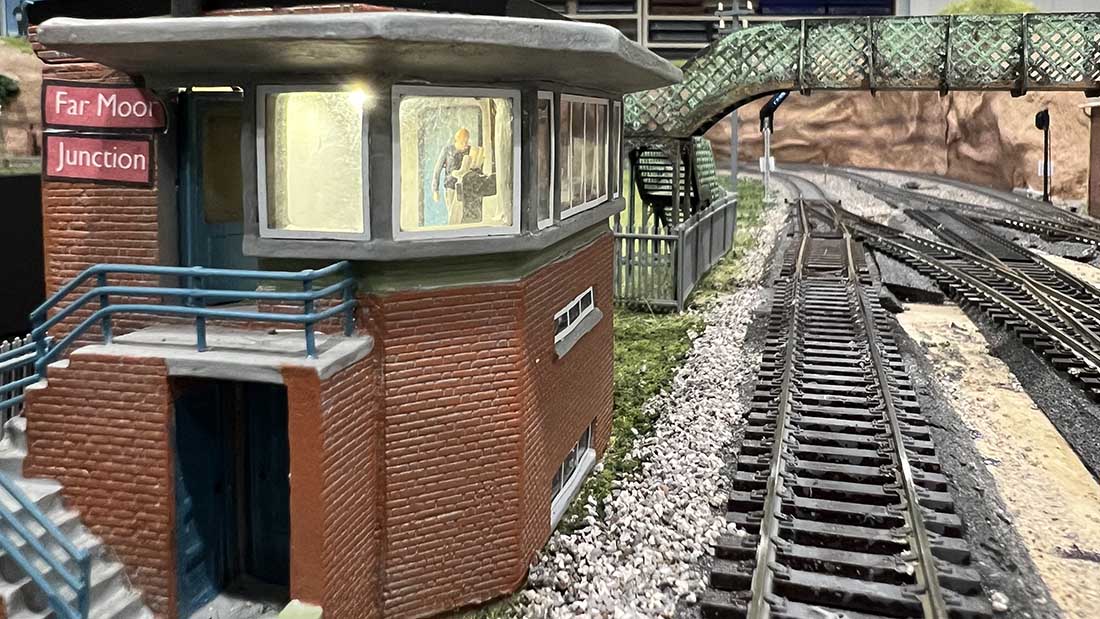
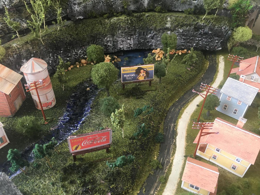
But in the same light, black and white pics also mask the amazing detail of Bill’s layout.
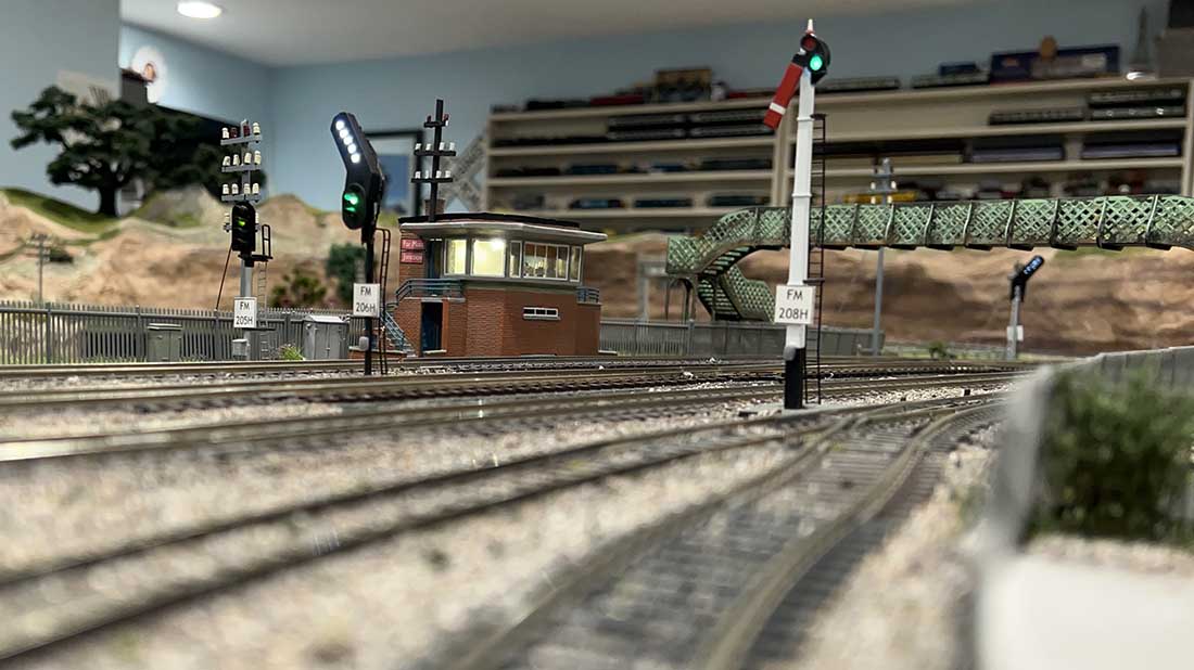
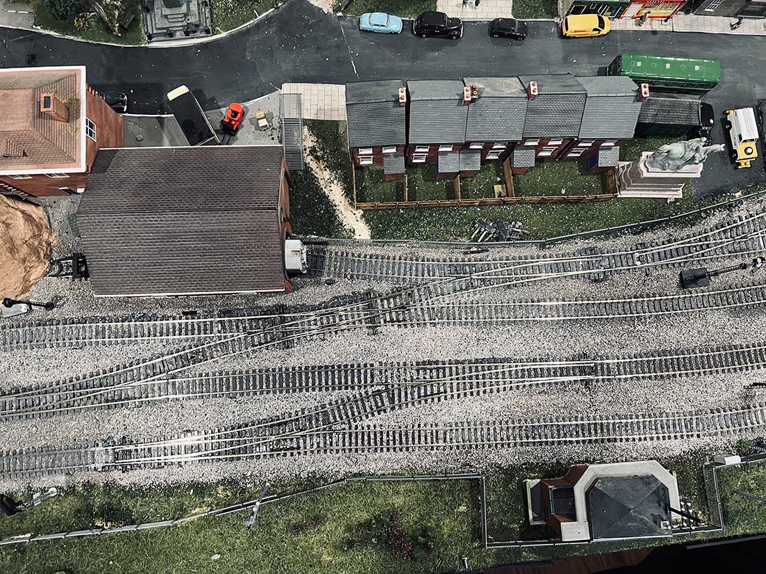
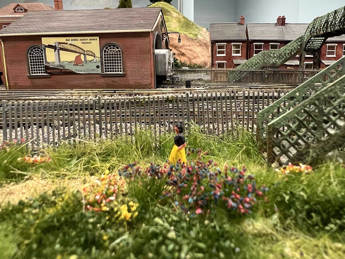
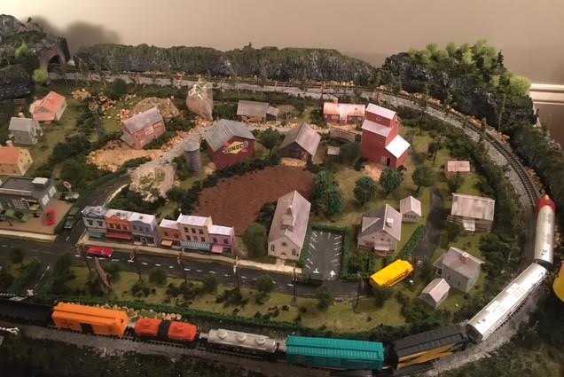
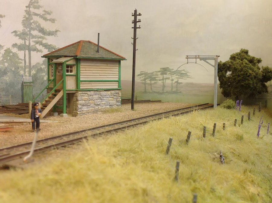
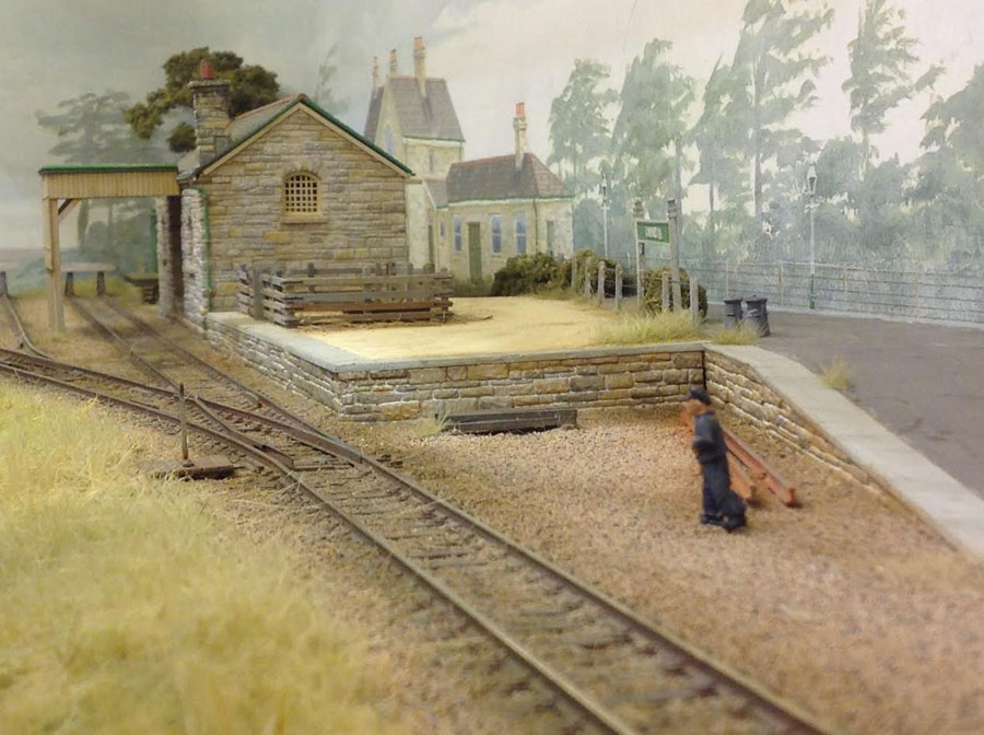
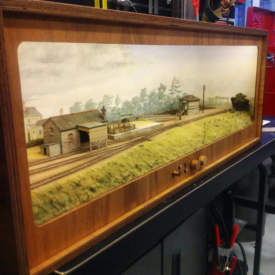
So let’s grab some pics and from a few of his previous posts so you can see them in all their glory.
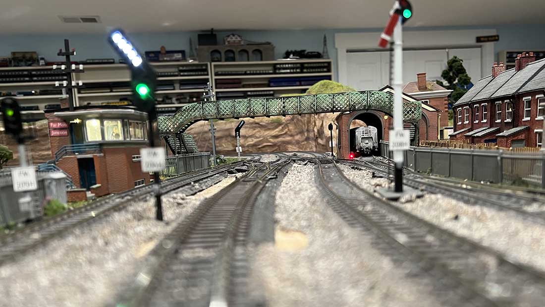
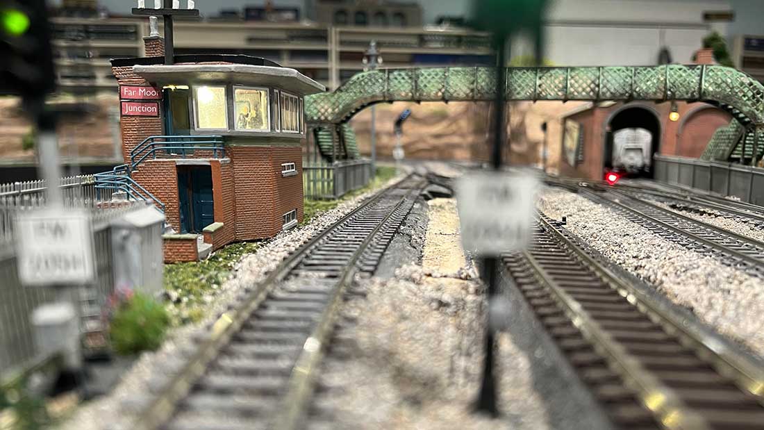
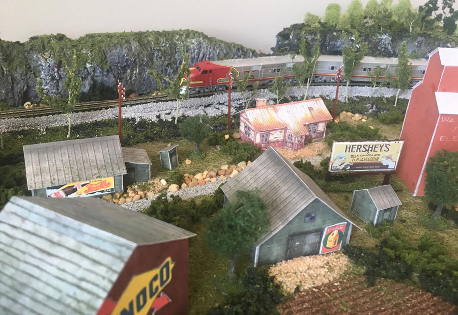
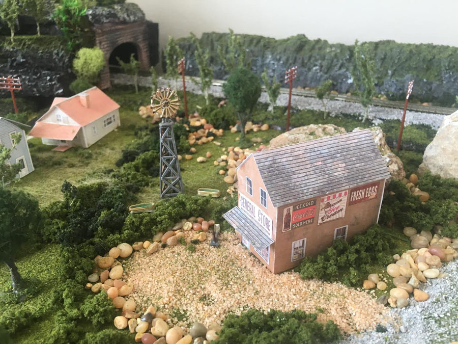
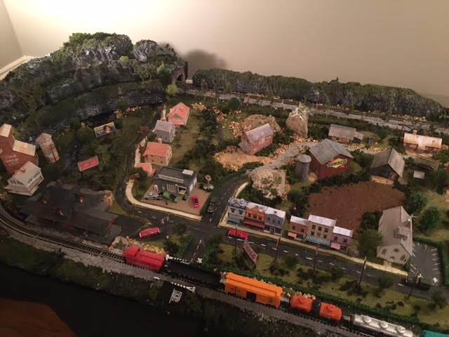
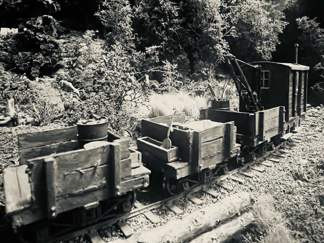
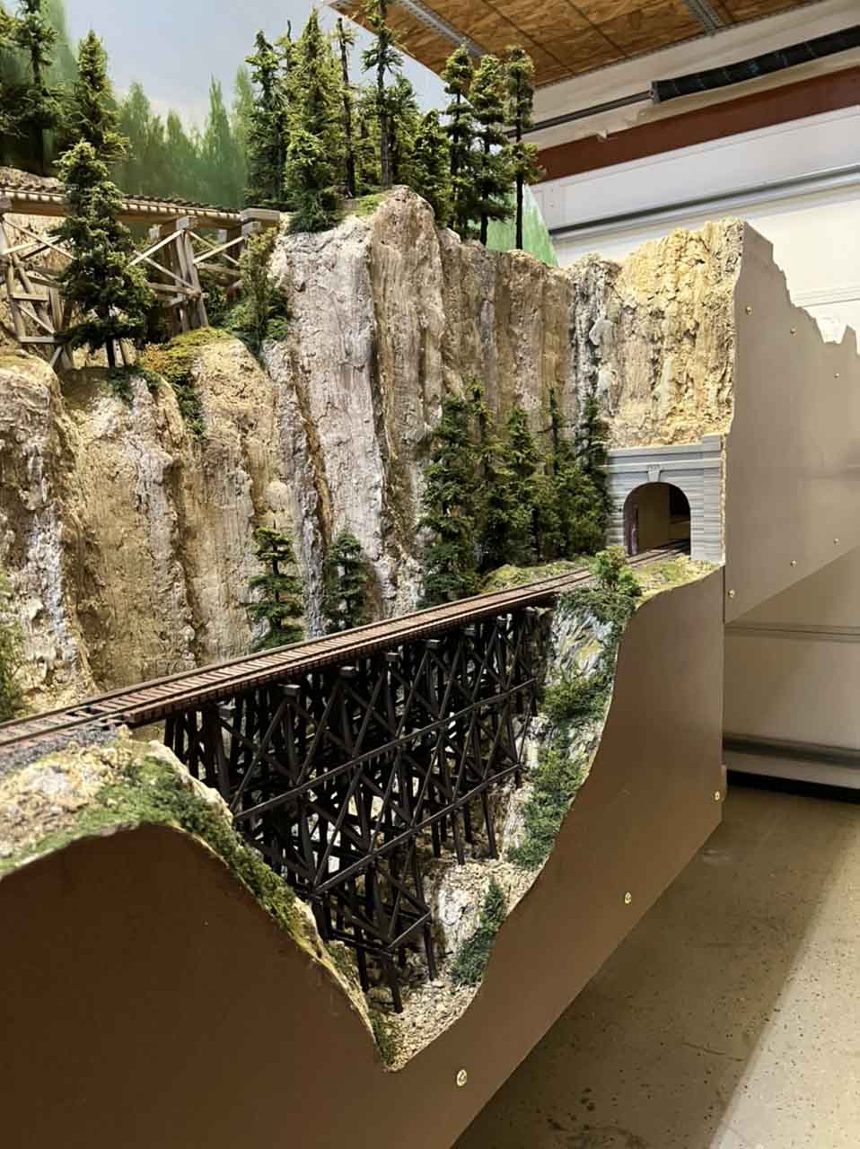
In this one – On30 layout – Bill wanted to create a vertical cliff – I think he can put a tick in that box. Amazing work:
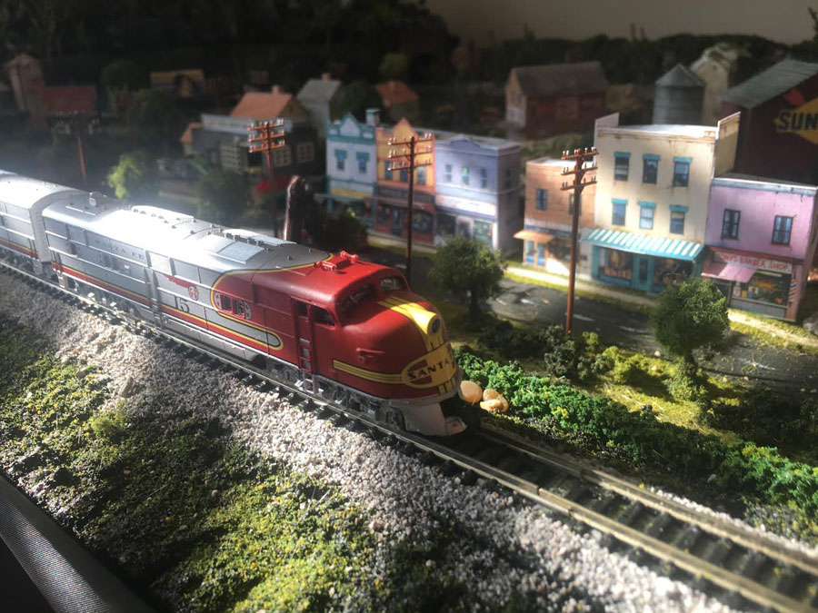
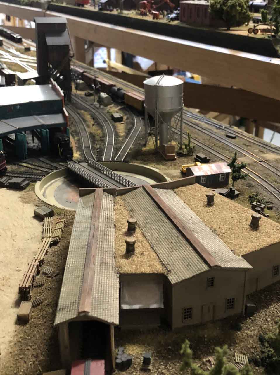
Bill has just as much fun with N scale too – you can see it here.
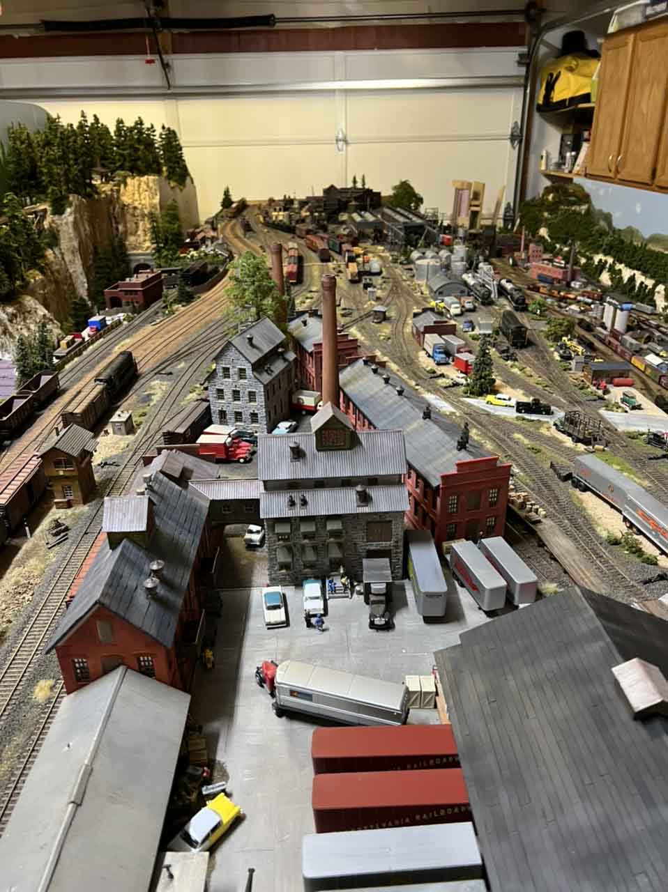
He’s a dab hand with HO scale. too:
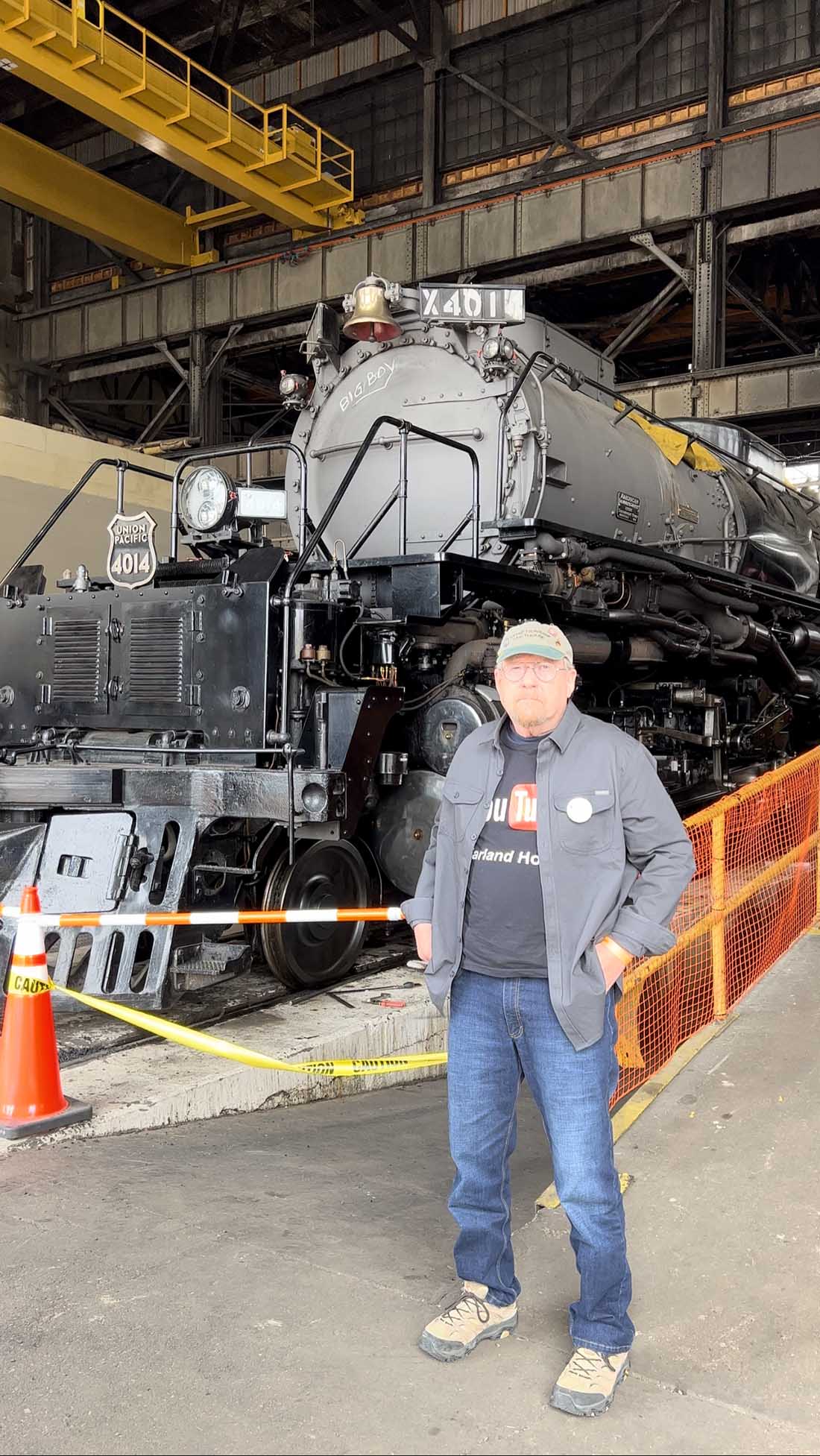
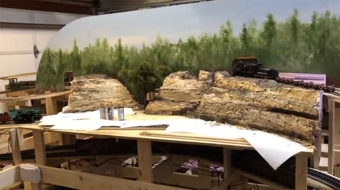
But perhaps, best of all, like so many of us, he does all he can to encourage others to start a layout – he has an excellent youtube channel.
Have a look at this post and see for yourself: How to make a cliff face.
A huge big thanks to Hall of fame member, Bill for sharing his vintage model railroad.
That’s all for today folks.
Please do keep ’em coming because it’s soooooooooooo quiet, I really do think I’ll be putting me feet up very soon.
And if today is the day you get started on your layout, the Beginner’s Guide is here.
Best
Al
PS More HO scale train layouts here if that’s your thing.
Need buildings for your layout? Have a look at the Silly Discount bundle.