Gary’s been in touch with his model train helix:
“Al:
Have never emailed you before but am slowing working on my double deck HO layout now that I am supposedly retired.
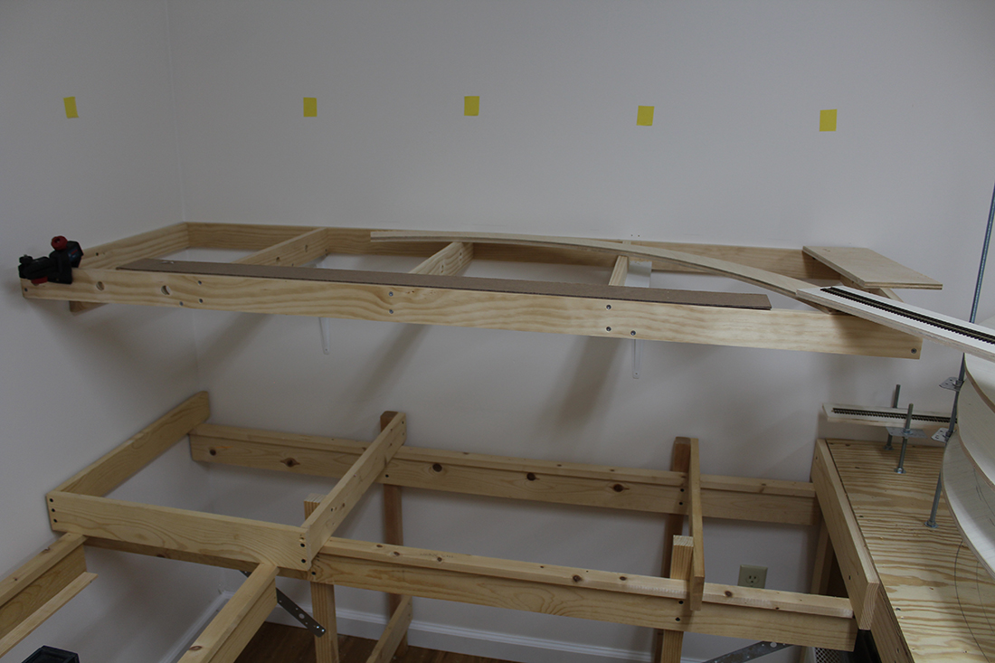
It’s an approximately 10’ x 18’ space in my basement. The levels are about 16” apart from top of level 1 to bottom of level 2, but the helix needs to go up to 19” to get to the top of level 2.
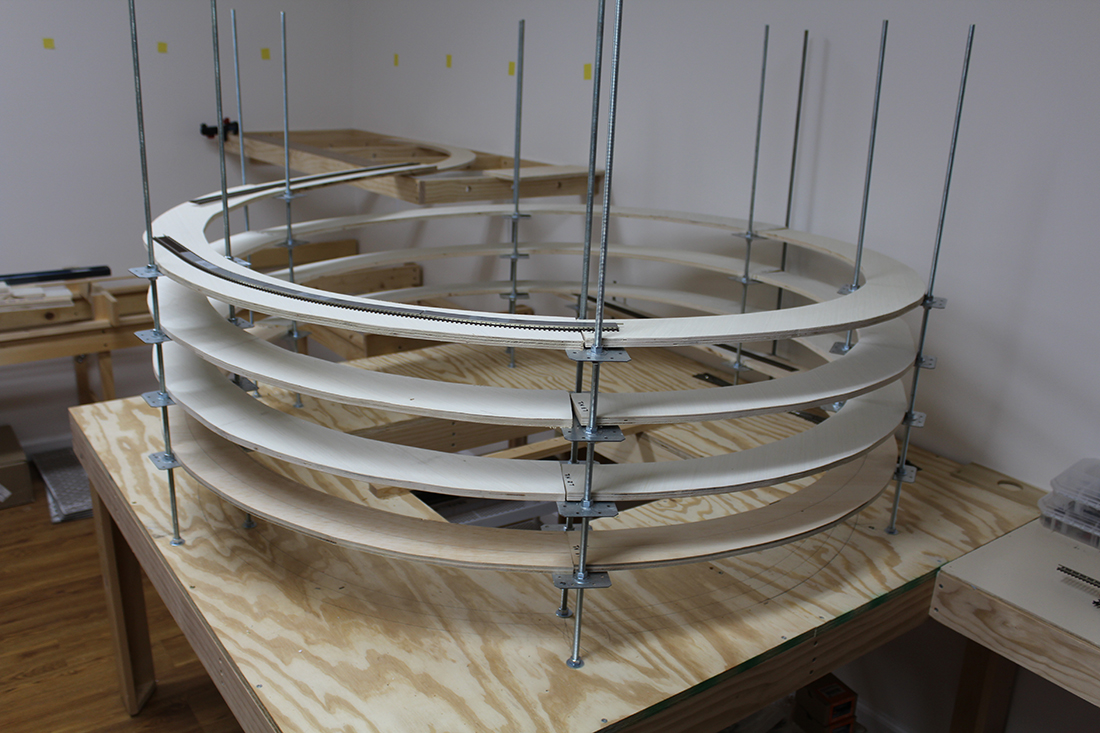
The model train helix is a 26” radius curve (as big as I could go) resulting in a 2% grade, which should be very manageable for my locomotives.
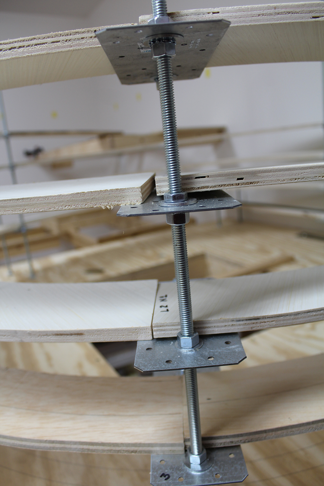
The supporting structure, as you can see, is threaded 3/8” rod with home store tie plates acting as the shelf for the end of the curves. They already have numerous holes drilled in them so I will use those to bolt the plywood roadbed to the plates.
Everything seems to be very stable so far, but have yet to run any trains. Each curve covers 120 degrees, so there are three pieces of ½” sanded plywood curves per level.
The construction allows me to automatically super-elevate the continuous spiral by simply raising the outside nuts a bit over the height of the inside nuts, nothing will have to be done to the track work itself. I read if you were going multi-level you needed to build the helix first, so that’s what I did.
I am modeling the Missouri Pacific De Soto subdivision during the late 60’s and early 70’s from Riverside to Cadet, MO and the extension to the Pea Ridge iron mine. I grew up in De Soto, the home of Missouri Pacific’s car repair shops.
I am still finalizing the track plan. Current idea is to start in Riverside on level 1 go through Horine (interchange with Frisco) then up the helix to De Soto.
Once I get all that done, I hope to go to layer three to get to Pea Ridge.
The De Soto subdivision run’s from St. Louis, MO to Poplar Bluff, MO as part of the Arkansas division – St. Louis to Little Rock. II will be using NCE DCC.
I hope you enjoy my model train helix and I am happy to answer any questions.
Gary
Hillsboro, MO USA”
“Alastair,
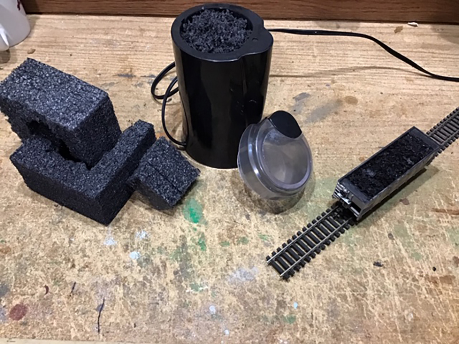
I commented on the recent blog entry regarding coal loads.
My neighbor was throwing out black styrofoam packed around furniture legs, which I grabbed. I then bought a used coffee grinder from our local thrift store. K-Cups have made these almost obsolete.
After filling the hopper, I spayed the top with hairspray. I can easily pull a long train of filled hoppers with a single Diesel engine.
Love your Blog
Marvin”
Now on to Jim – who has been kind enough to answer some questions on his last post, which is here.
“Hello Alastair
Several of the people who responded to my latest work on Starrpoint, had some questions regarding several areas, NCE SWITCH8 MK2, the BI-COLOUR LED work and my transfer table.
First lets touch on the NCE SWITCH8 MK2. GEORGE ZAKY wanted some information on what goes into installing one. So for George here is my reply:
Here is a picture of the NCE SWITCH8 MK2 board
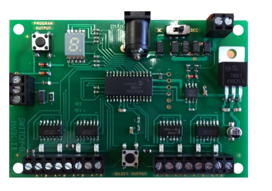
When you look at the board, you will notice several terminal blocks on the board. The one at the upper right is for power. This is where you place the power wires either from the track, or from a separate power source.
To the immediate left of the power terminals is the selector switch for DC or DCC operation, which ever you are using.
To the extreme left of the board is a terminal board with three screws. These are only used if you plan on using toggles to throw the turnouts as well as the automatic system. I never use these since I only use the automatic system for the turnouts.
On the bottom of the board there are 2 banks of 8 terminals. It is here were you wire the turnouts. They are numbered 1 a b, 2 a b and so on until you get to the end of 8. You need two wires from the turnout, one for closed and one for thrown. The best way to wire the turnouts for proper alignment is to look at the turnout you are going to wire.
Now for tortouise switch machines, you only use terminals 1 and 8. So take a wire from terminal one of the tortouise and connect to terminal 1 a, take a second wire connect that to terminal 8 at the tortouise and connect that to terminal 1 b and then at the NCE SWITCH8 MK2 board. You now have one turnout wired. The rest follow the same wiring pattern.
Now you will notice two buttons on the board as well. The one on the bottom centre of the board allows you to toggle between the wiring points. A LED will light indicating the terminal selected. You will also notice that in the upper window a number will appear indicating the terminal is selected.
Now for the fun part of all this, you can program all of the turnouts with individual numbers. To do this first push the center button on the bottom and select the turnout you want to program.
Next push the button on the upper left corner, this is the programming button. You will notice that a flashing “P” will appear, indicating you are ready to program the selected turnout. You will need your DCC throttle to program the turnout. You can use any number you wish up to 3 numbers only. Push SWITCH on your throttle, select the numbers you wish to use for that turnout, and you will notice on the throttle either a “T” of “C” appear on the throttle screen. Simply choose the opposite alignment and you have now completed your first turnout programming. Congratulations.
ROLAND ALDRIDGE commented on using the BI-COLOUR LED’s for the turnouts. I did use them for all of the switches, however the way you mentioned and noted on the instructions from Tortouise I had issues so the way to solve the problems was to first wire all of the turnouts with the power wire on a continuous loop. All eighteen turnouts were wired in series, with only one wire to the main panel and connected to a DC power source. This eliminated the voltage drop at the turnout power. Next RED and GREEN wires from the tourtouise were brought back to the main panel and connected to the individual BI-COLOUR LED’s. You are right there was a lot of wiring doing it this way, but found it beneficial. No issues with the turnouts.
MARKUS MUETSCHARD wanted information regarding the WALTHERS TRANSFER TABLE.
Well let me tell you, I was devastated the day the transfer table stop working. I found the issue to be with the electronic board that controls everything on it. I contacted WALTHERS, and HELJAN ( who originally made the transfer table for Walthers ) to purchase a new board. None are available. So now what needs to be done? I did not want to remove the table and have to fill in the space with wood. And I could not use a turntable to utilize the buildings in the Diesel area. I had to find a way to make it work. So I put on my electronic thinking cap, and came up with a solution. A DC power pack could be used to control the movement of the transfer table deck. So that solved that problem. But what about the lighting? AH there was the ultimate headache. There are two lights for the table and one that blinks indicating the table is moving.
So what to do? Well there was only one solution, design a electronic board to control the lights. Here is a picture of the board that I designed and built to handle the light issues
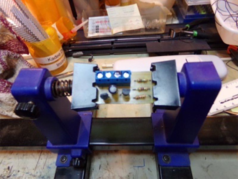
The board contains two transistors, one NPN and one PNP. Three resistors are necessary, 1K, 100 meg and a 47 ohm. A 2.2 ohm capacitator, and a four terminal wire connector.
And it works. Now I can use the Transfer Table again with added excitement.
I hope the information and answers to all of the above questions are helpful.
Jim Sr
Starrpoint RR”
A big thanks to Gary for sharing his model train helix, and to Marvin and Jim.
When it comes to a model train helix, I’m always reminded of Lawtrences helix.
That’s all for today. Please do keep ’em coming.
And don’t forget the Beginner’s Guide is here if you want to take your first step with your own layout.
Best
Al
PS Latest ebay cheat sheet is here.


Gary Like the design of your helix. The mounting of the track base on the plates will allow very fine adjustment to ensure even running and track entry and exit levels onto the main tables. Also looks very quick to make and assemble. Well done a great design.
I haven’t started on my layout and the last one I built was 1960! This stuff is much more complicated and I ever imagined.
The problem with building the complete helix before laying track is a big problem that you will run into. The space between any level and the next level up (probably about 4 inches) makes is very difficult to work on any level. When I built my helix i worked on the first level before installing the second level. My recommendation is that you take all the layers off (should not be too hard with the way you built it) and finish each layer one at a time. Remember the helix is part of the layout. So not only is the track layed down but should also have ballast.
Please Guys …. run some trains will yas ?
Hey Gary, I used the same plan for my Lionel Super O layout. You really want to lay and test the track as you build each level. Looks good so far!
Gary,
A guy told me some years ago that a helix needs to have super-elevation thought out. One is to elevate outer rail higher than inner rail. This is done in real world due to car weight not causing the inner rail wheels to lift and derail.
However, consider that in modeling the cars are not burdened with freight load, so the reverse may apply. That is the tongue pull from each light weight car to the other in the consist may pull the cars to the inside and have the consist “wreck” inside the helix.
So, you may decide to provide a slight elevation to the INNER instead of outer rail to aid the consist in each car pulling the next tighter to both inner and outer rails.
I believe Lionel did this in one of their very early displays.
Just some thoughts to your helix. You will need testing thoroughly before anchoring the degree of any elevations.
Here’s to your helix success.
I hope your plywood stays true and does not flex up or down between your supports lay the track and run it and run it and run it till it works. Personally I love spline roadbed build a layout had no track problems for 20 years I have never been a fan of plywood. Good Road bed on the layout says you’ll love it for life and no Constant Repair. Or time now is the last time later so you can do other things.
(Comment for Gary)
Very nice work on your helix. Please send updates when the trains are running and really using that clever helix. It should look great. I have one suggestion, as you mentioned adjusting the helix; watch for any incremental changes to your track joints. Any raising/lowering will produce small changes to your track length. Good luck with your project.
Hy Gary, there is a better way to make a helix, I think. You start with a flat piece of plywood which is square at the largest possible track diameter. You find the center and install a dowel, or a thread bobbin. Then using a string tied to the dowel you stretch to the start point with a marking pen. Then as you go round you create a cut line which gradually moves inward each rotation.. The size of the dowel is the amount of track width (circumference). Then you cut with a jig saw on the line and get one continuous spiral. When you lay track, all levels are easily accessible from the outside land there are no breaks to align in the plywood. After mounting you can fill in the inside of the spiral with cardboard to make it look like a mountain. You will need a short bridge at the top. I believe that your current spiral will work and will have continuous problems at the breaks when running trains. In any event, good luck and its great that you are going ahead with your dream. From Bob
Gary
WOW- Run passenger trains thru first. It looks close but I think you have clearance.
Marvin- Thanks.
Jim
Many thanks for that and the other answers. Keep us posted on updates.
Aside from Big Al you’re my new best friend.
Al be safe and well
George from LI, NY
Jim Sr,
Will those boards work on DCS (AC power) systems?
Concerning Gary’s helix, use a lock washer to secure the bottom bolt from moving (I think Gary did that). To avoid problems where two section ends join, position your metal brackets to roughly the height you want. Then screw a plywood plate about 6” long beneath the two end sections to secure them tightly down so they can’t cant upward. Then secure the plywood plate to the metal plate. Now fine-tune this section’s height and move on
OR Place a second metal plate (instead of plywood) on top of the two end sections to tightly screw the two section ends down. To offset the upper plate’s thickness, trim away (reduce) the thickness of each section’s end to offset the plate’s height. The top metal plate serves to snug the two ends down tight so they can’t cant upward and create their misalignments.
Question for Bob. As you wrap the string around the dowel to outline a single spiral, you note the radius decreases with each turn. In HO, if you use a 4’x8’ piece of plywood, the 48” width will accommodate the minimum recommended radius of 22”-24.” Each subsequent turn around the dowel will quickly bring you closer to the smallest radius your equipment can handle. Wouldn’t it be better if you wrap the string around the dowel until the marker reaches your minimum radius, then unwrap the string outward until you reach the end of the board? Just a thought.
To Gary, the adjustable height, no matter how you attach the section together, is a great idea, Much easier to adjust then blocks of wood.
Thanks to all for the helix comments. Yes, I will build from the bottom up and will experiment to determine how much flexing I get from the plywood. I also appreciate the ideas on the joints and reverse super-elevation. My time period dictates that there was only one MP passenger train still in operation that passed through De Soto, the Texas Eagle which was a rather short consist. Since De Soto was MP’s primary freight car construction and repair facility the focus will be on freight traffic. Also, many foreign roads used De Soto for repairs for derailment damages in central and SE Missouri, so I Katy and Frisco nameplates were quite common. Regards to all. By the way I worked for MP for several years prior to the U P buyout, so have some Eagle blood in my veins.
Gary, just what exactly are those tie plates normally used for? I havent seen them before.
I have enjoyed model RRs since I was in grade school and looked forward with such eagerness to working with my Dad to set up the Christmas layout for the whole family. I also enjoy Al’s wonderful public service, HOWEVER, I just can not grasp the need/rationale/purpose of a helix. I’m also struggling with all of these hi tech/electrical boards!! Guess this hobby has passed me by and now I’ll just have to read old MR magazines!
Gary, I like your helix design. Using 3/8″ threaded rods was wise. I’ve seen some helices that only used 1/4″ rods and I think they could flex too much. My only recommendation would be that you not place the plywood joints directly over the metal plates supported by the rods. I would put the joints away from the rod locations and secure them together with either a 6″ piece of plywood on the underside of the joint or with a pair of metal plates that sandwich the plywood ends in between them to maintain alignment. Looks like it’s going to be a great layout.
Jim, Your explanation of the NCE switch controller was very clear and your solution to the transfer table problem was sheer genius! You are obviously comfortable designing and building your own circuits. That’s a great skill to have as a model railroader. I am envious. 🙂
Where did you get the plates and did you have to drill out the holes for the threaded rod ?
to george, you are right, good idea to work backwards. The dowel in HO should probably be only 1/2″ diameter or smaller which changes 1.57″ per wrap. Actually the spiral could have a smaller track support as the track can be located at the outside edge of each spiral. Its all part of the fun of planning track. One nice thing about the spiral is that the inner supports can be simple boards without adjustment. The sprial has only two transitions, one at the top and one at the bottom providing for very smooth operation. Although I like Garys helix, I really think that long term operation will be a problem. Bob
Hello Bob S., Andy here.
Unless you are particular to the spiral in the Polar Express movie, I am not sure if your concern about Gary’s helix is justified. I have been using my Helix with Lionel Super O track (31″ rad) using the same threaded rod concept for over three years with no issues. I even included the super elevation that this design so easily allows. My biggest issue was the tight radius required a simple circuit to automatically increase speed for uphill traffic while reducing downhill speed using a relay and two transformers with appropriately set voltages. Truly old school, but that is why I love this hobby, I can live in whatever timeframe that I and my railroad desire. And yes, I deal with high tech electronics every day at work, so it is kinda fun to see what my postwar equipment will allow me to do with current day expectations. Still working on my version of DCC with my AC powered three rail gear. Will keep you posted.