Jim’s been in touch again – this time with how to install HO scale turnouts.
“Hello Alastair
Jim from across the big pond here in Buffalo NY, and it has been a long time since giving any update on Starrpoint Railroad.
I have been converting the layout from DC to DCC operation. It has required a huge rewiring undertaking.
There is over 500 feet, of new wiring on the layout and there is more to do. From wiring all of the track points, the 18 tortouise switches, signaling all of the buildings with new LED or SMD lights in them. The LED’s need a resistor to control the voltage going to them while the SMD’s have resistors built into the light strip.
There is a diesel and a separate steam area on the layout. The Diesel side has a Walthers Transfer Table. It is an old version that Walthers had some years ago.
The electronics for the table stop working, so I had to find a way to make it work. The Electronic board controlled the lights and the movement of the table deck. And since there is no way of replacing the board, I had to come up with one, so I built a board that will handle the lights.
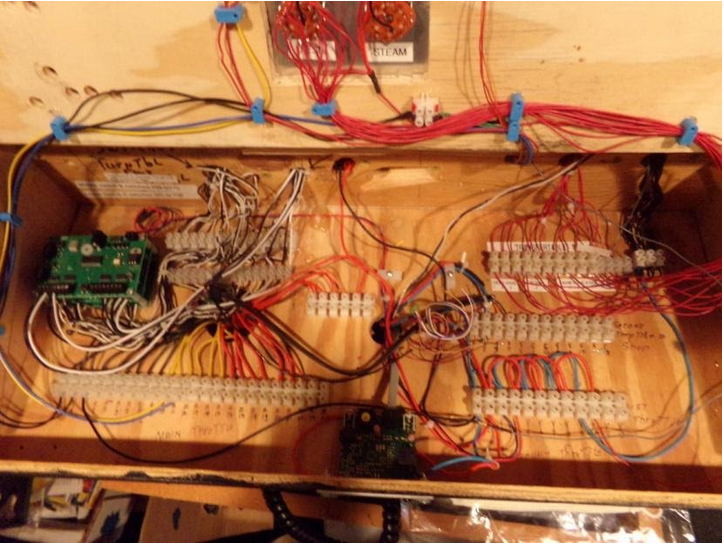
Here is a picture of the board that I built for the light issues:
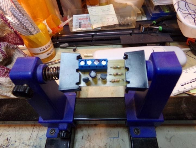
The board has wiring for the lights, and tracks. Since the old board was able to work a blinking light on the table to notify movement, I had to build the board with transistors to handle that part, and a part to handle all of the other lights.
For the transfer table to operate I found that a DC transformer will work to move the table back and forth, but will not automatically stop at a given point. I can stop the table, at the proper spot for track alignment. So that took care of the Transfer table operation and light issues.
In the Diesel Transfer Table section, there are 12 tracks leading to various points.
Three of the tracks for the Diesel House, three for the Car Shop, one track for the Maintenance Shop, Three tracks for Diesel holding and two tracks for the Diesel Refueling Station. All of these tracks had to be converted to DCC and controlled separately.
There is a 6 position Rotary Switch controlling these tracks. The Rotary Switch has two separate power connections that allows for 12 power feeds. This is accomplished using a Double Pole Toggle Switch ( position A and position B ) There are indicator LED’s showing which track is operating.
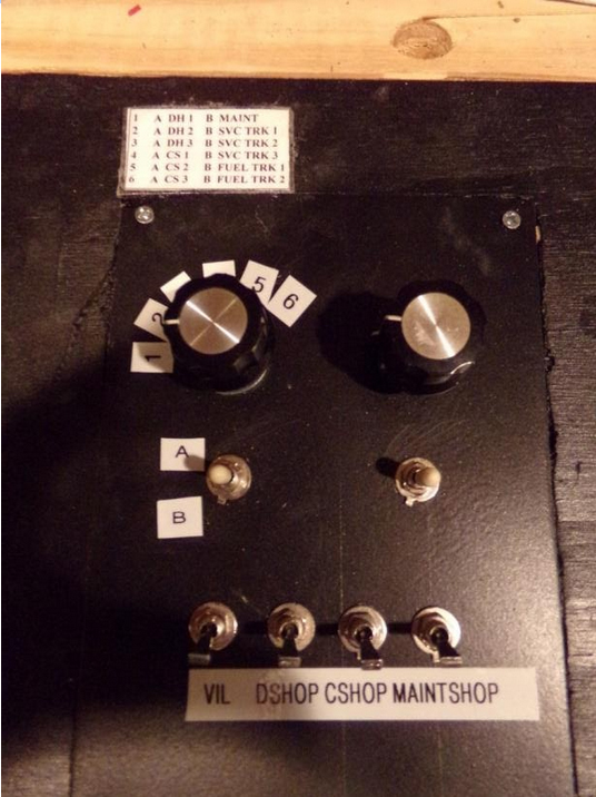
Here is a picture of the top of the main panel showing the rotary switch and control toggle. The left rotary switch is for the Diesel area. On the layout drawing I have placed LED’s to indicate which track is in use. The reason I did that, all of the Diesel Locomotives will have sound, and I did not want all of them to come on all at once, the noise level would be hard to handle.
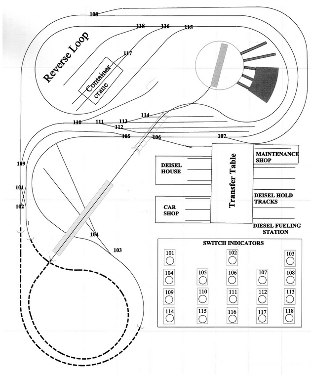
I made a drawing of the layout to indicate all of the turnouts. Since there are 18 HO scale turnouts I need a way to show the turnout position either open or closed. So on the drawing I added a SWITCH INDICATOR for the turnouts and numbered each turnout on the layout drawing.
Each one is a Bi-Colour LED ( RED / GREEN ). I installed 18 light tubes to hold the LED in place. Each of the indicator light centre’s had to be carefully cut out for the LED to show through. The Layout Drawing was LAMINATED to protect the drawing and to enhance the LED Light.
In order to have the Bi-Colour LED’s work correctly, they must be wired a specific way. Below are the items you need to complete this project.
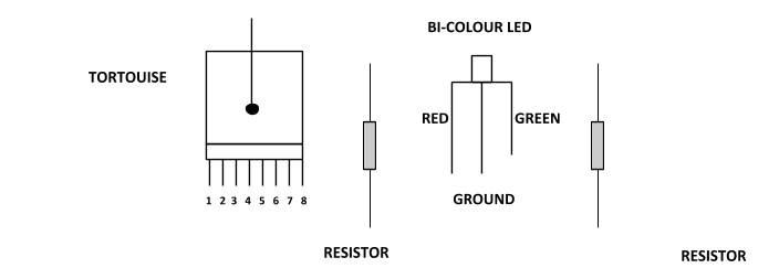
On the tortousie switch machine, there are 8 terminal points, 1 and 8 control the switch only. Terminal points 2 and 3 plus 6 and 7 are auxiliary terminal points.
Terminal points 4 and 5 are auxiliary power points. These two points can be used to supply power to signals, or track usage.
Here is how to wire the BI-COLOUR LED.
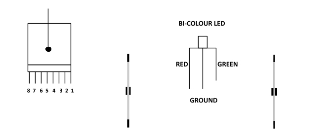
Take a DC power wire to power point 4
Take a wire from #3 to the resistor that will control the Red side and from the other end of the resistor to the Red side of the LED
Take a wire from #2 to the resistor that will control the Green Side and from the other end of the resistor to the Green side of the LED
The Ground part of the LED can be wired in series with other BI-COLOUR LED’s.

Below is a picture of the NCE SWITCH 8 MK 2 DCC boards. There are three of them that control the 18 turnouts. The boards are located in the upper left hand corner. The arrow below points to their location
Here is a picture of the top of the Main Panel with the Switch Indicators
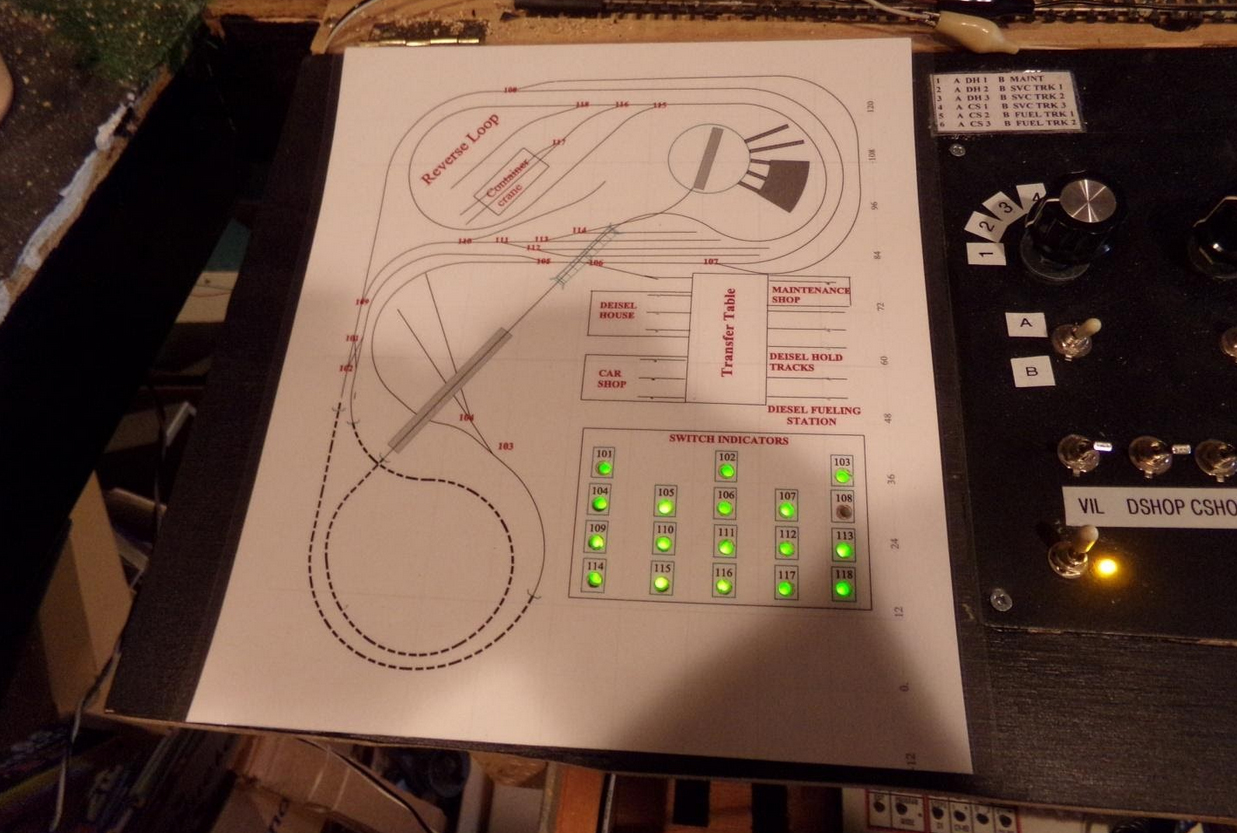
At the time when this picture was taken, turnout 108 had not been wired as yet. It is not wired for the panel. Turnout 108 has four functions: Control the turnout points, Indicate on the Main Panel, control the Signal Tower and Track Power.
The Signal Tower indicates which track is in operation beyond the turnout. All trains can enter the area that is controlled by the Signal Tower and will not continue past if the turnout is not aligned correctly.
Below is a picture of the Signal Tower.
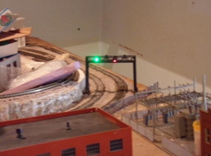
As you will notice, the track that has the Green Signal the train on that track can proceed past turnout 108, while a train entering on the outside track will stop at turnout 108 to prevent an accident. Once the turnout is set to the correct position on the outside track, then that train can proceed.
All of the above wiring took a long time to complete, but the work involved was worth it.
Most of the buildings have lights in them. On the panel that contains the two Rotary Switches, there are four toggles that control the Building lights. The one marked VIL controls all of the village and future city building lights.
The Toggles marked DSHOP control the Diesel house lights, C SHOP the car shop lights, and MAINT the maintenance shop lights. These lights can either be on all of the time or on only when being used.
I will be sending an update showing all of the building lights when they are lit. I want to complete the city portion of the layout first that will take some time.
I hope you enjoyed what has been completed so far.
Jim.”
A big thanks to Jim for taking the time to show us how to install HO scale turnouts.
In fact, there is another very good post on HO scale turnouts by Cameron:
And if your trains stop on the turnouts, and it’s driving you mad, this post will help:
It’s always good to see a layout morph from a tangle of wires and plastercast to a scenic railroad scene (His first post is here).
That’s all for today folks.
Please do keep ’em coming.
And don’t forget the Beginner’s Guide is here if today is the day leap out of your armchair and start planning your masterpiece.
Best
Al
PPS More HO scale layouts here if that’s your thing.


This is some wiring and well done for getting it all to work .The finished control panel looks really nice .May be you could do a video clip of showing how it works ???…….WELL DONE
What a splendid setup Jim
So well thought out. The rotary switch is a good idea to save panel space.
Like the rotary switch set up …well done all round ..Dangerous dave
Jim well done. A mammoth task to strip and rewire the whole layout. Good to see that all connectors are labelled. I particularly like the light gantry showing that the track is available and stopping the train on the other line. I assume when the green goes to red the other track will proceed. Very clever. If I were to make any comment it would not be the wiring but the control panel indicators. You need to refer to 2 areas.i) the track plan to get the turnout that you wish to use then ii) the light array to see the status of that turnout. I wonder if it would be easier to have the indicator light within the plan next to the turnout plan. I assume that as you use the layout you do not really have to refer to the plan but mistakes do happen and it would be a pity to have trains crash into each other. Just a thought.
Crumbs, a lot of thought and great work has gone into that and must have taken an age to get right.
Nice job. What’s next. I hope you have a map of what you have done. It looks like you are a electrical engineer. Well done would like to see more of your layout if it’s like your wiring it’s got to be fantastic.
Beautiful wiring job!
Jim
Awesome job and well installed. Please enlighten us more about the NCE, what parts were installed, cabs, etc for us rookies into DCC.
Stay well
George from LI, NY
An alternative – and much easier – way of wiring LEDs for Tortoise switch machines is to use the kind of bi-color LEDs that are, for example, red when powered one way, and green when powered the reverse way. They have only two leads. You wire them in series with the tortoise power, and then when the tortoise is powered in one direction the light is red, and when it is powered the other way it’s green. Many fewer wires – and if a wire breaks, you get an absence of the light to indicate that that tortoise isn’t working.
It Just Boggles The Mind!!!!
Wow, what a project to rewire the entire layout. You did an awesome job!
Amazing work- so organized.
Great work Jim, puts my spaghetti wiring to shame. Andrew in Oz
500 plus feet of dc wiring. i would look into using ring engineering it can be used on a dc to dcc conversion with out rewiring and is compatible to standard dcc.
Great… first time I see someone having done a transfer table… I’d like to see some details of how you have done it.
Very nicely done Jim – both the photos and your explanatory text. Your electrical skills are obviously more up-to-date than mine. The only question I had when viewing the layout plan and transfer table is this: is the transfer table long enough to accommodate an engine and car to be transferred to the car shop? If not, how do the cars move on and off the transfer table? I don’t know if this is a real problem or just my “what if” mind at work. 🙂
Beautiful wiring job! Keep us posted as your layout progresses.
Will, in real car shop operations there isn’t room on the xfr table for both a car an engine so they use a pulley system w/ a winch on the table or just brute force with the aid of a car mover lever.