Dean’s been in touch with his model train lighting post:
“Al,
I’ve been updating my lighting (and other electricals) on my N-scale Conejos Valley Railroad.
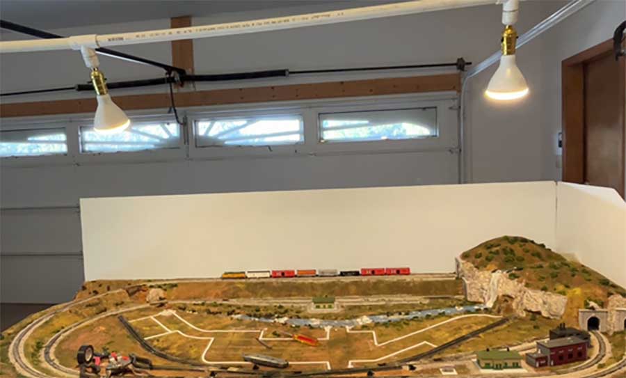
I’m getting back to the layout as you can see from the placing of tape for pouring plaster roads (shown in the first photo), a project I’m now working on. More to come!
This entry deals with how I built a more permanent lighting system. It could be adapted to any small train layout as you can see.
Here’s how I made it using standard lighting and PVC plumbing parts from a big box store.
The first shot shows the final double lights.
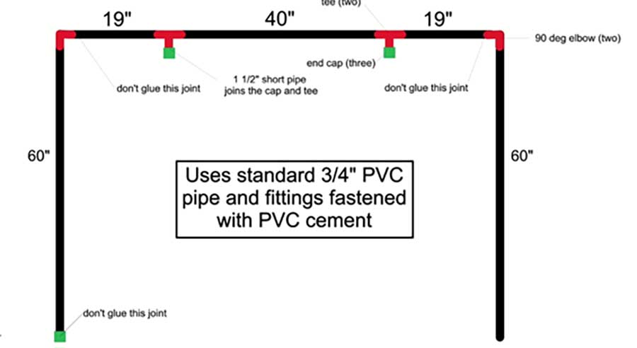
The next photo shows a diagram of the dimensions of pipes using ¾” PVC parts.
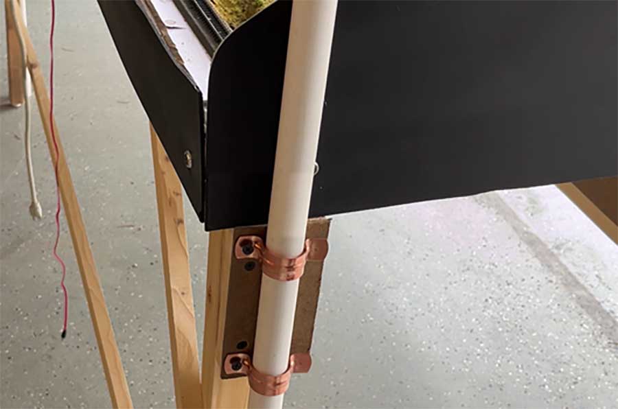
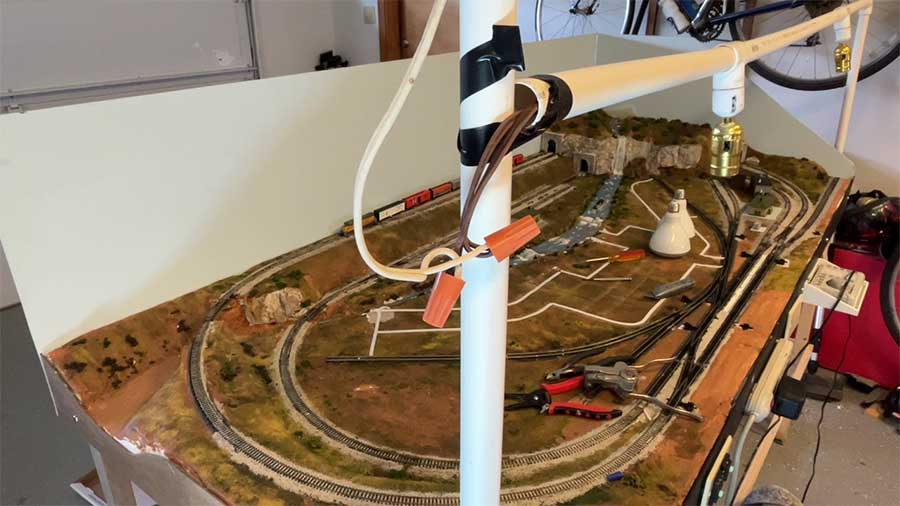
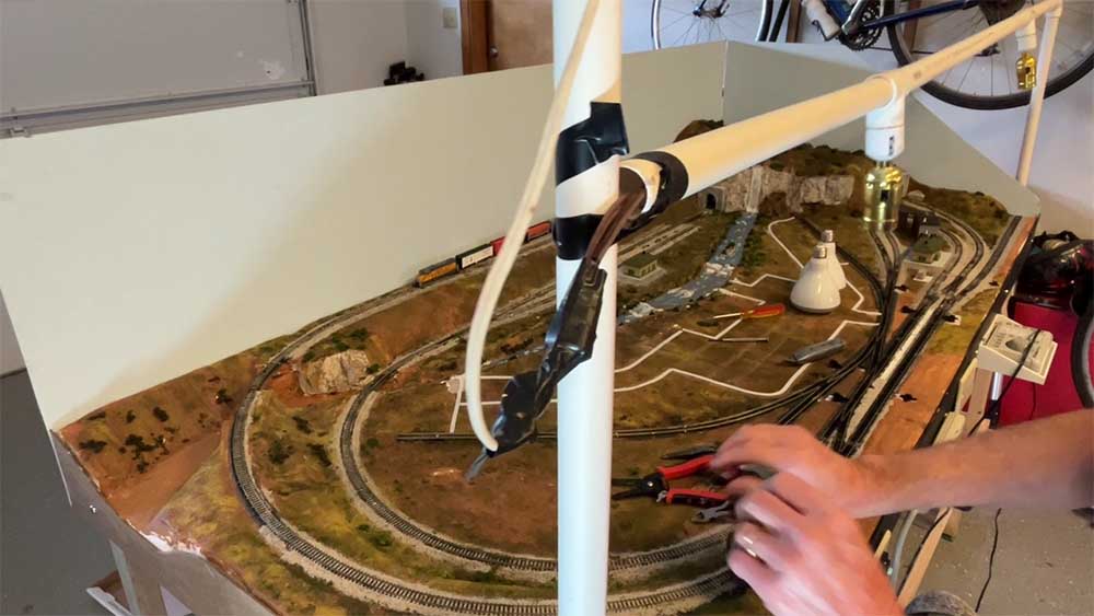
The next shot shows how the two vertical pipes were held to the sides of the model train layout. This is a tight friction fit which allows the height of the lights to be adjusted.
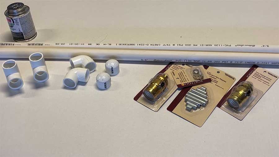
Here is a photo of the parts I used. How to wire the lighting fixture was shown on the back of its package.
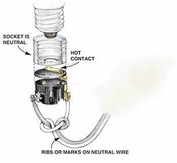
Here is a lighting diagram for wiring the standard lamp fixtures. The wires run through the pipes going to the left. In the US, the wire used for the neutral is marked with a molded line or ribs.
The pipes were temporarily held together with tape for support. The two wires from the lamp fixtures were connected to an extension cord with the female end cut off.
This extension cord ran down the vertical pipe through a drilled end cap. Wire nuts were used as shown in the photo below.
Be sure to connect the three neutral wires (marked as above) and the three hot wires together.
Model train lighting:
The wire nuts were then wrapped with black electrical tape for insulation and the wrapped wires were pushed back into the pipes.
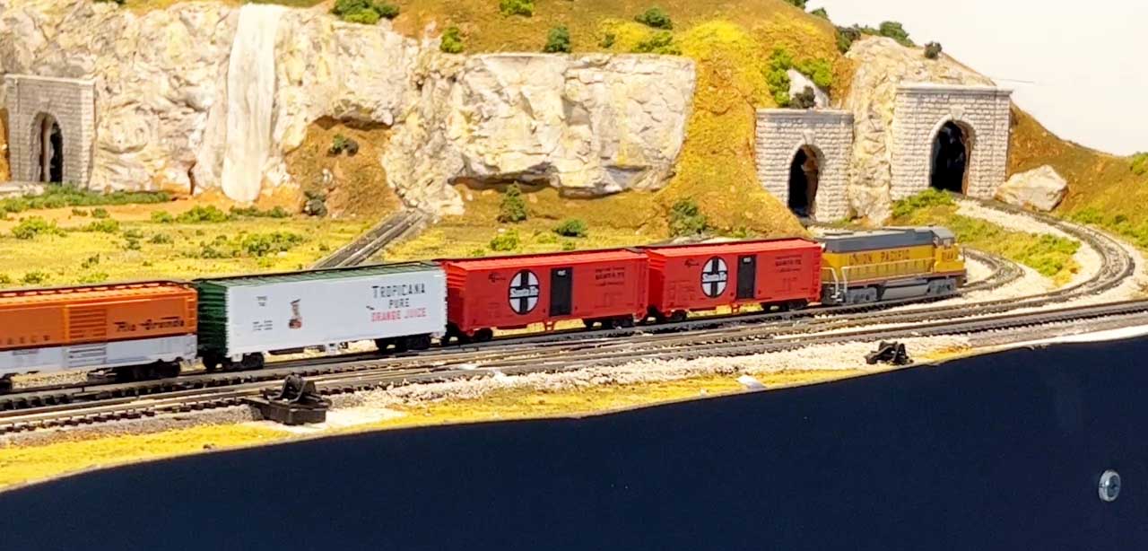
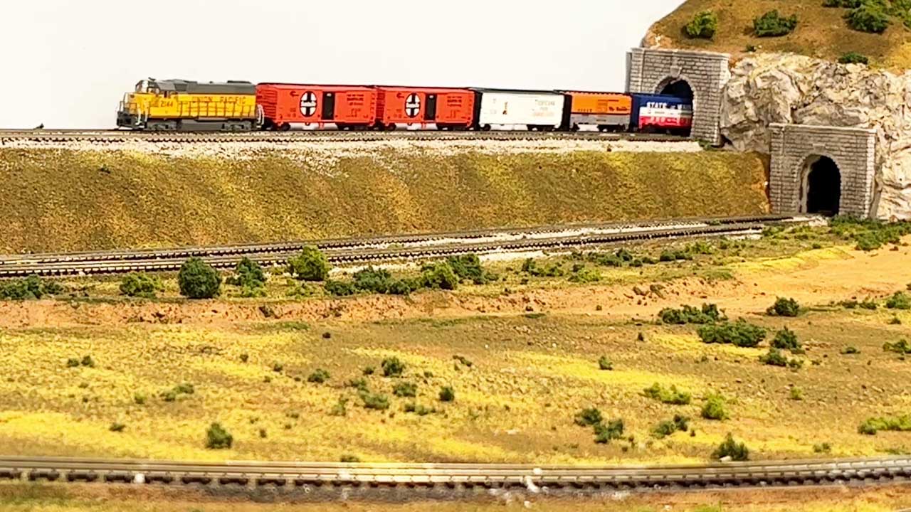
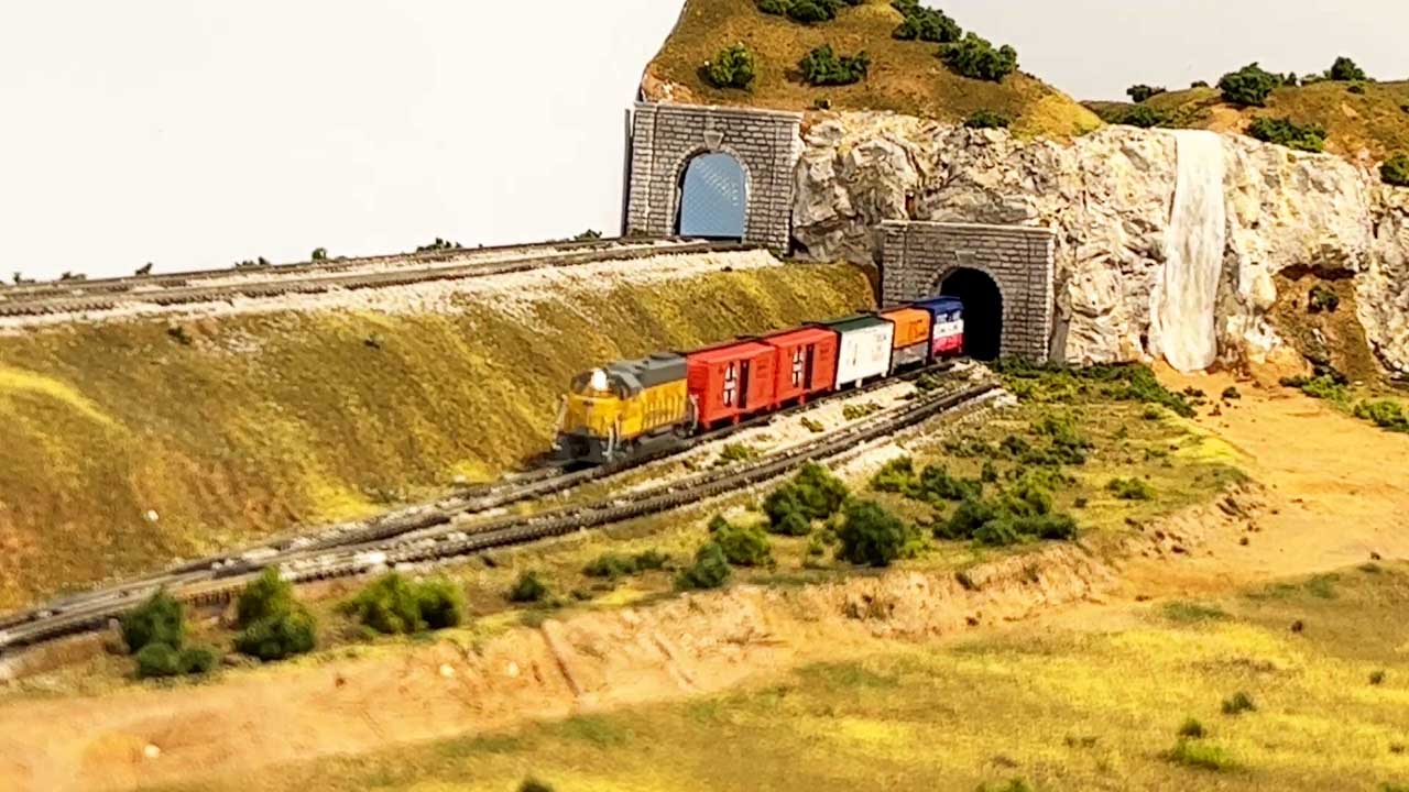
Finally, here are three photos which show the even lighting with these lights.
Al, thanks for all you do for this hobby.
Dean from New Mexico”
A big thanks to Dean for sharing his model train lighting post – there is lots on the blog about adding lighting to the actual layout, but I think this is the first on shining a light on the actual layout.
Here are just a few of the posts on LED lights:
Adding lights to model railroad buildings
Connecting LED lights to power
LED lighting for your model railroad
That’s all for today folks.
Please do keep ’em coming.
And if today is the day you get started on your layout, the Beginner’s Guide is here.
Best
Al
PS More HO scale train layouts here if that’s your thing.
Need buildings for your layout? Have a look at the Silly Discount bundle.

Dean,
Very well done!
I especially like the fore-thought on disassembly.
Do you see disassembly happening often, or just when the layout gets taken apart?
Regards,
Ross
I did something similar over my work bench, except I used the gray electrical conduit system. It’s advantage is the system junction boxes have covers that are screwed on, only I used the typical lamp base sockets without the covers. For wiring I used replacement lamp cord and a switch that plugs into a socket.
Great Idea Dean! You gotta love PVC pipe you can do so many things with it, other than its intended use, gas pipe is another one of those wonderful products. Keep the updates coming Dean and the rest of you too, an thanks Al, for keeping us all connected. Maybe one day I can put my ideas on paper and create something really cool like the rest of you.
Don’t do this in the UK, it is against no end of requirements of our legally required standards and we have 240 volts!
Nicely done. A great idea to achieve lighting that’s practical, affordable and mobile. Thanks for sharing.
Jim AZ
I like lighting up everything. It adds warmth and ‘action’ to small layouts in any gauge. Nice work here for sure.
Can’t say a lot with this one. The light socket diagram is spot on for polarity at least. I don’t believe this to be any sort of risk but still haphazard. Should be at least plugged into ground-fault if in basement. Not sure with those sockets/floods if left on might melt the PVC.
Can this be removed from U-tube, may get sued for liable? No, I’m serious….
Rich
nicely done. very nice layout.
Neat idea for improving the layout lighting Dean! I did notice some sag in the top PVC pipe between the tees for the lamp sockets which could get worse as the heat from the lamps softens the PVC. The gray schedule 80 PVC pipe is designed for use as electrical conduit and has thicker sidewalls than schedule 40 PVC. That might be less likely to sag under the weight and heat of the lights. Of course, using LED bulbs would generate less heat than incandescent bulbs. I like the western look of your layout.
I have a very large (16 X 30) O scale layout that requires a lot of light, so I replaced the existing light fixtures with two fixtures that each have 4 can lights. That gives me eight 65 watt can lights that do an excellent job of lighting my layout. I have a dimmer switch that allows me to vary the light depending on the circumstances of my operating sessions.
Good basic idea but not in this manner in the UK.,
Why use PVC water pipe when electrical conduit pipe is available? Wiring projects to meet code requirements is not that difficult and will provide peace of mind.
Thanks for the comments. I couple pointed out that this would not be allowed in the UK. I’m not familiar with the UK codes, but I do know them in the US since I once had a homeowner’s electrical license to wire a house I was building. What I did was basically the same as wiring a lamp socket. And all the parts can be legally purchased in the US.
One person was worried about melting the pipe. The lights I used were 15-watt LEDs which each pull about 15/120 = 0.125 amps. So the total current is 0.25 amps. The 14 gauge wire I used is rated at 15 amps. And the power loss in the wires is miniscule.
Also, the lights are plugged into a power strip with a circuit breaker, and everything is plugged into a ground-fault interrupter Should be fine.
I would have used galvanized pipe clamps instead of copper, cheaper
The Critic