Bob’s been back in touch with some more details on terminal strip model train wiring.
He’s been kind enough to write a response after all the comments on his last post, which is here.
“Alastair,
In response to comments on my last post here is some info on my terminal strip model train wiring.
First off I am not an electrician. I spent 14 years in the Infantry and 38 years as a programmer and systems administration.
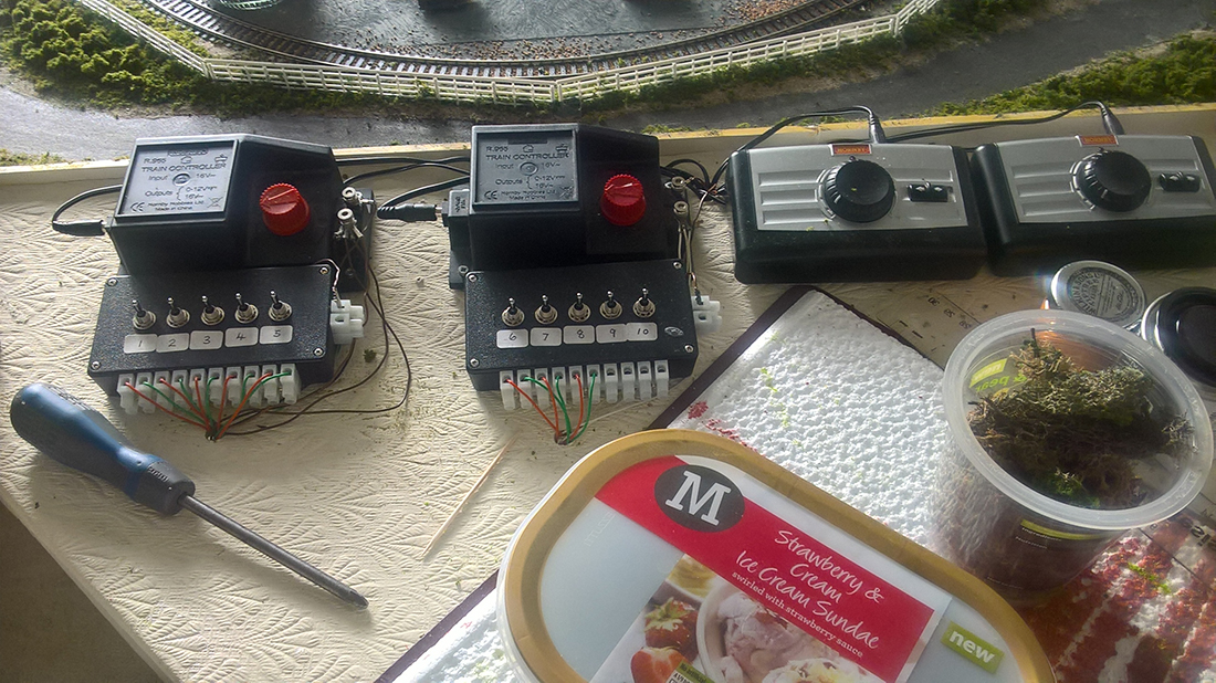
The wiring looks daunting, but it is quite simple if you take your time and do not rush.
I have found that ‘Spaghetti Bowl” and “rats’ nest” wiring come from rushing.
Right now, my track wiring is looks messy because I am testing to make sure everything is working. The key is to make sure I clean it up once I verify the everything works, and I will. I am taking my time this go around.
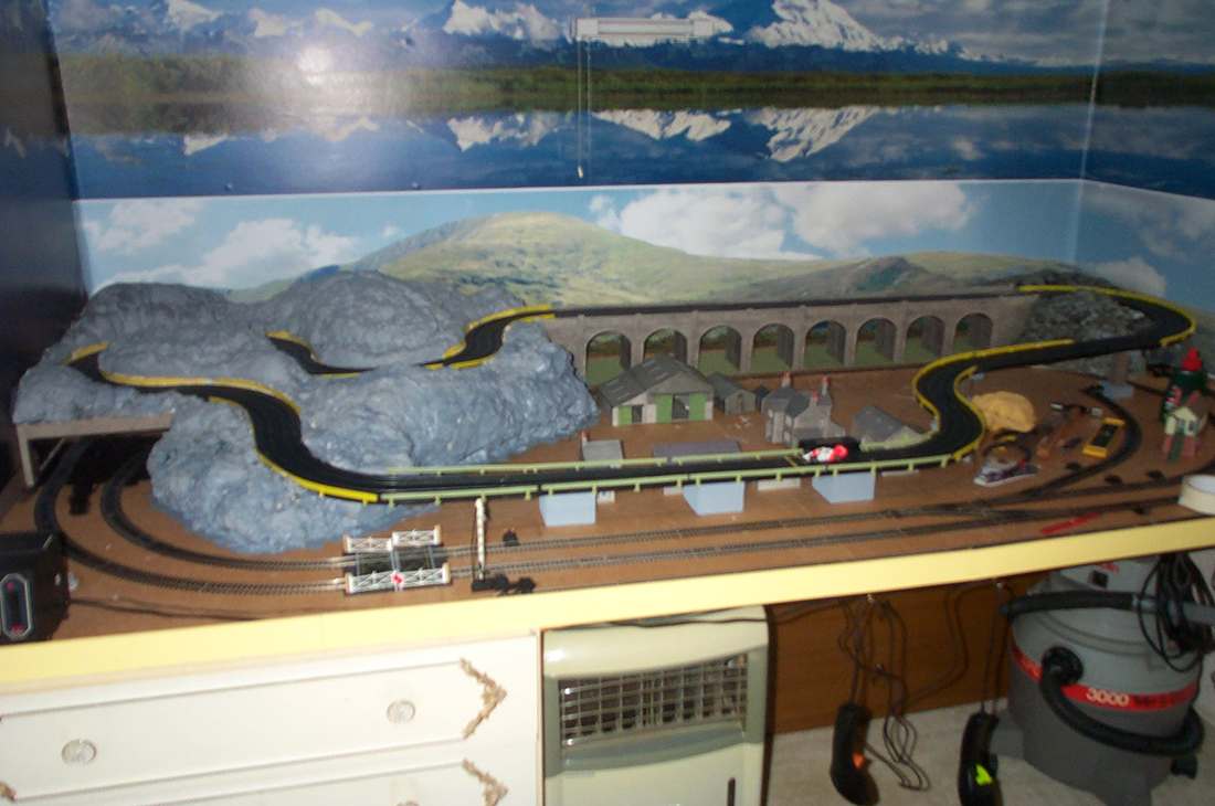
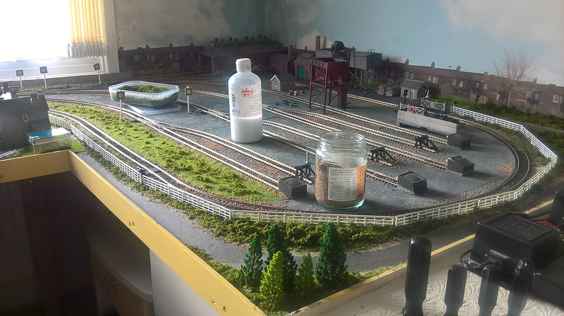
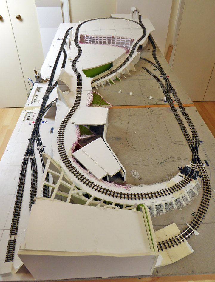
The first picture shows my track plan. There is a double main that has four signal blocks on each main. The first block of each main is at the top between the tick marks. The outer main blocks are numbered counterclockwise 1,2,3,4 and the inner main blocks go clockwise 1,2,3,4.
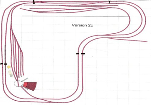
I am using Arduino to read the IR sensors and to control the signals.
There is an IR sensor at the beginning and the end of each block and a three head signal mast at each end of each block.
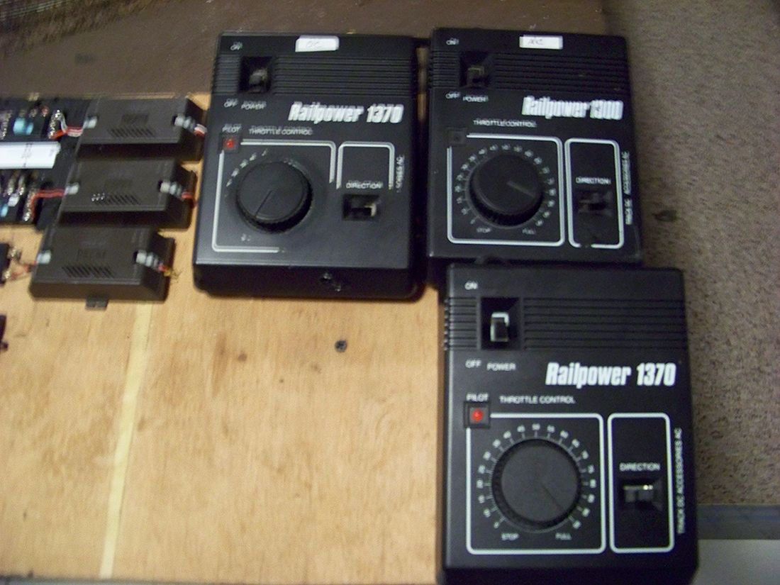
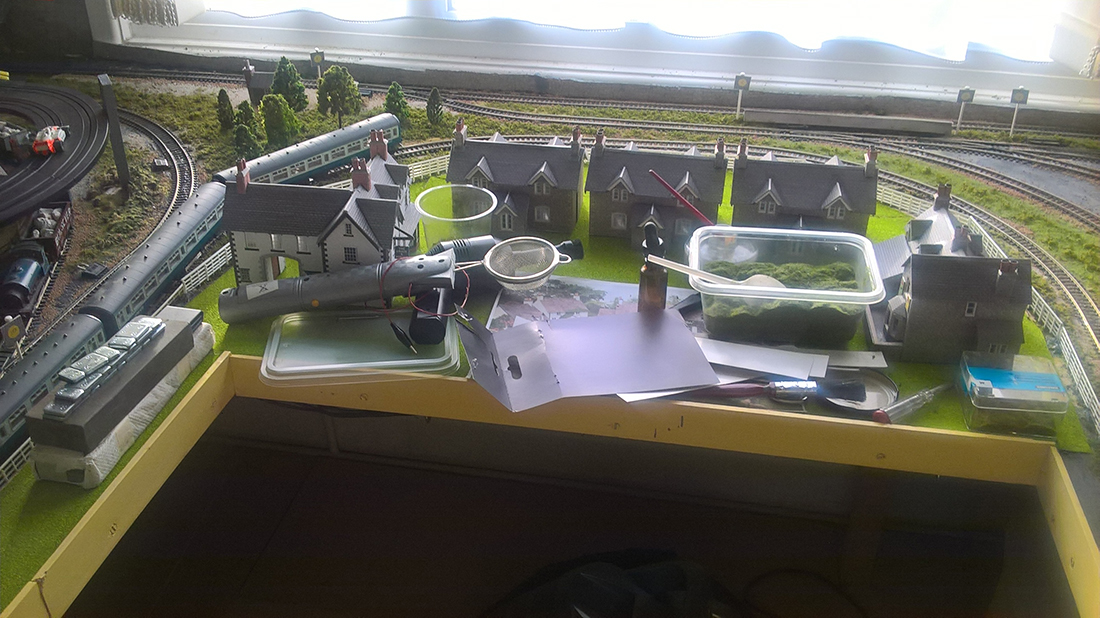
The second picture shows how I have mounted an Arduino and wired it to three terminal blocks. Each is wired to communicate with the next block(Block A) and the previous block(Block B) and an intersecting tack(Block C).
There are three places where there are tracks that allow access into the block between the sensors.
Note in the upper right quadrant there are tracks entering the mains.
At the bottom of the layout there is an access track for the turntable.
In the upper left quadrant, the track from the yard joins the inner main. Each is wired for three sensors and three signal lights because of these four mid-block access points. These four tracks are the Block C respectively. That is enough about the blocks. On to the wiring.
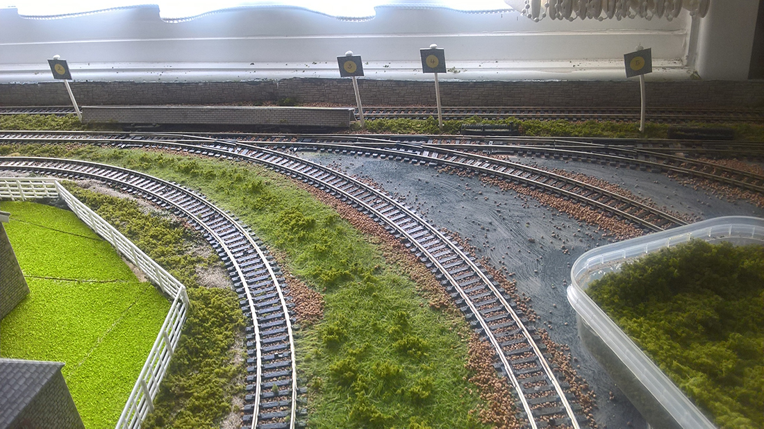
This picture shows the wiring of one of the eight main blocks. The Block C sections are controlled slightly differently but have the same wiring setup.

Terminal strip model train wiring 1:
Pin Connection
1 Positive connection 5v
2 Positive connection for Sensor1 (Black wire)
3 Positive connection for Sensor2 (Black wire)
4 Positive connection for Sensor3 (Black wire)( Note: This gets use when there is a spur in the middle of the Block: e.g., yard entering the main , track from turn table connecting to main.
5 Positive connection for Signal 1 (Black wire)
6 Positive connection for Signal 2 (Black wire)
7 Positive connection for Signal 3 (Black wire common on the signal) (Note: This is used when there is Block C)
8 GND connection from Arduino
9 Common GND for Block A
10 Common GND for Block B
11 Common GND for Block C (Note: This is used when there is a Block C)
12 Not Used
Terminal strip model train wiring 2:
Pin Connection
GND connection
Sensor1 data connects to analog pin A0
Sensor2 data connects to analog pin A1
Sensor3 data connects to analog pin A2
BlockARec connects to analog pin A2
BlockBRec connect to analog pin A3
BlockCRec connects to analog pin A4
Red – Signal 3 connects to digital 4
Yellow – Signal 3 Connects digital pin3
Green – Signal 3 Connects digital pin 2
Block A send connects to digital pin 8
Block B send connects to digital pin 9
Terminal strip model train wiring 3:
Pin Connection
Red Connection for Signal 1 – Connected to digital pin 4
Yellow connection for Signal 1 – Connected to digital pin 3
Green connection for Signal 1 – Connected to digital pin 2
Red Connection for Signal 2 – Connected to digital pin 7
Yellow Connection for Signal 2 – Connected to digital pin 6
Green Connection for Signal 2 – Connected to digital pin 5
Red Connection for Signal 3 – Connected to digital pin 13
Yellow Connection for Signal 3 – Connected to digital pin 12
Green Connection for Signal 3 – Connected to digital pin 11
Block C send Connected to digital pin 10
Block B send Connected to digital pin 9
Block A send Connected to digital pin 8
Maybe too much info but I hope it is useful and convinces some to take the plung.
Bob in Virginia”
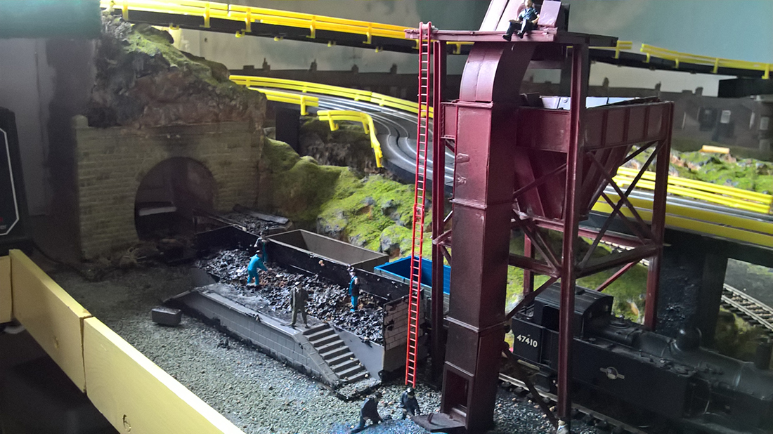
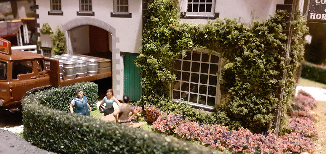
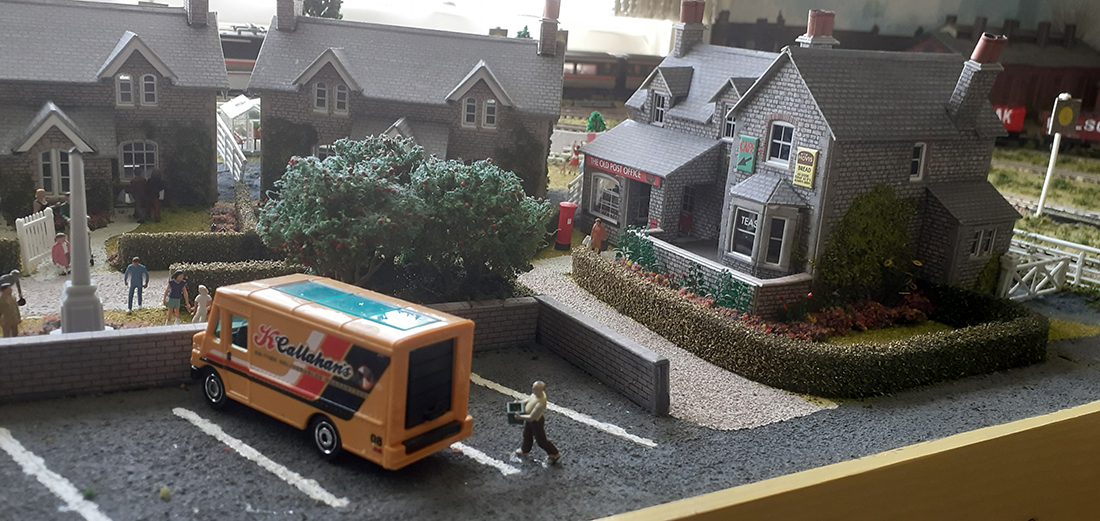
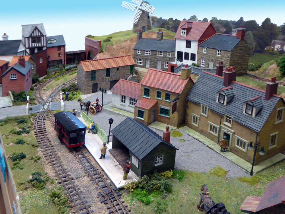
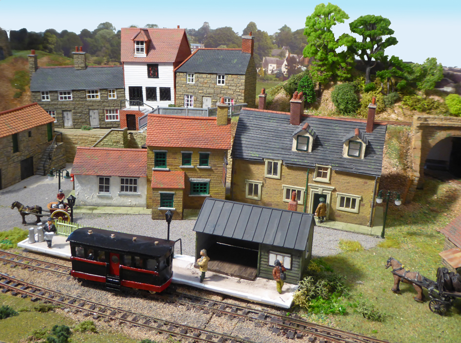
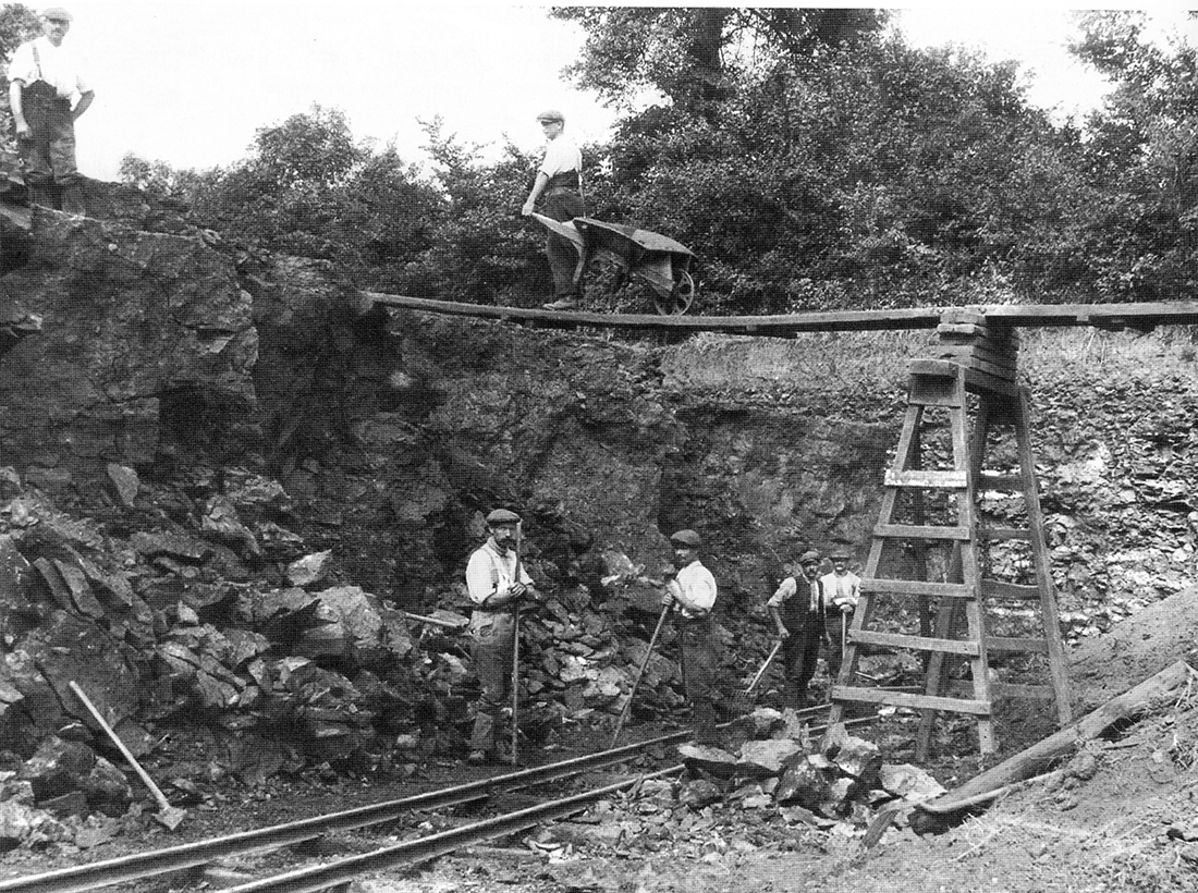
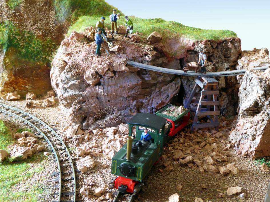
Now on to Keith – and I absolutely love what he’s done, particularly the scene of the men working:
“Alastair:
I have not seen any British narrow gauge railways in your blogs so I thought your readers might find this of interest.
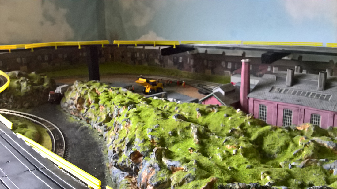
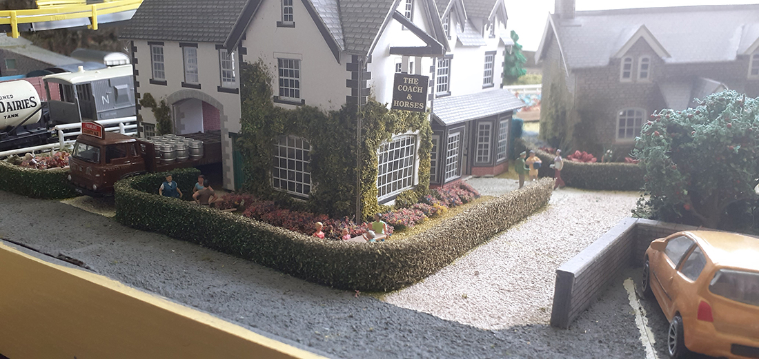
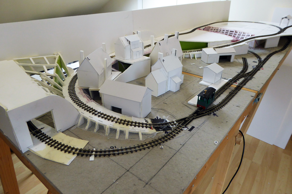
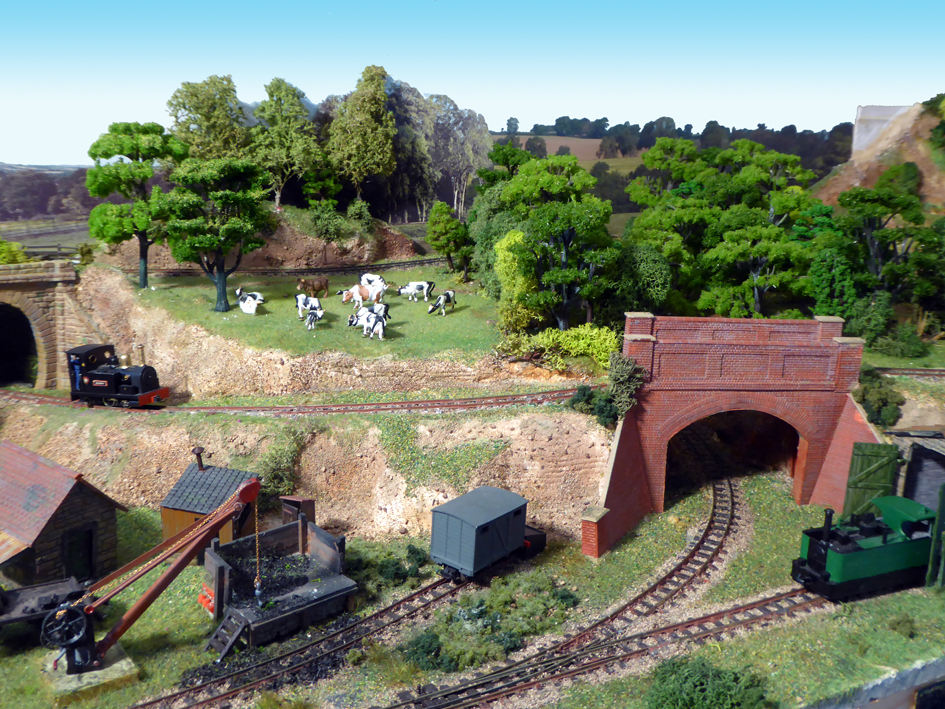
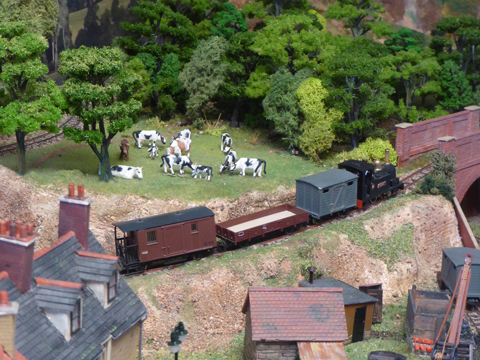
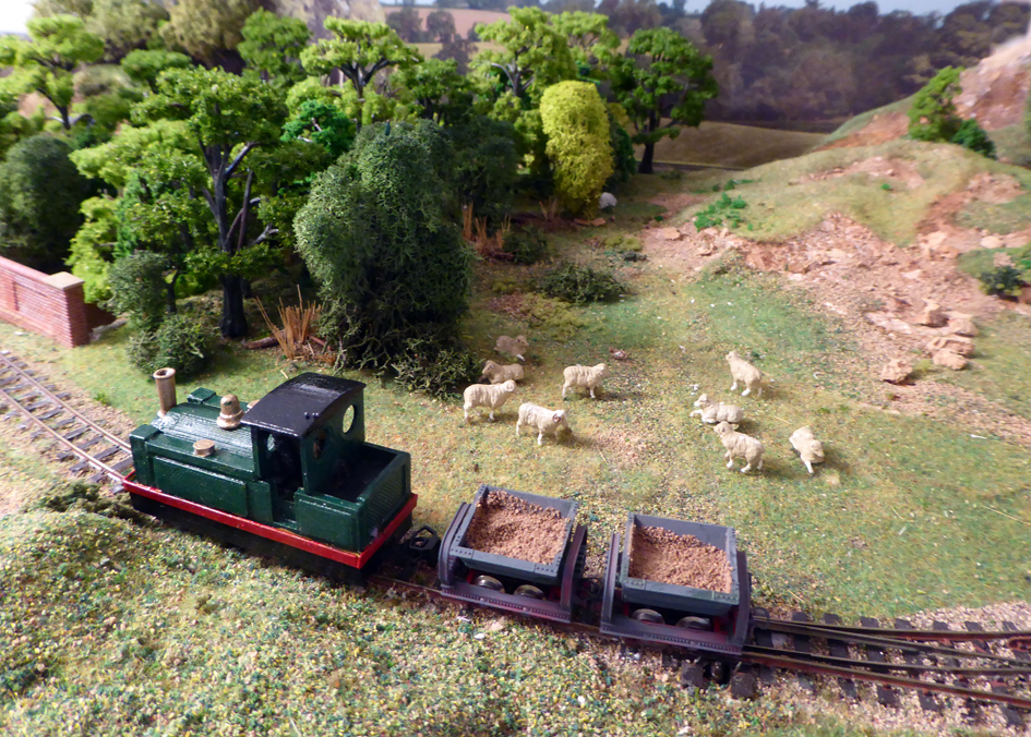
The Sibford Quarry Railway is a 4mm scale narrow gauge layout set in the British Cotswolds.
There is no railway in the Sibfords where I live but you can find Sibford Gower and Sibford Ferris on the map either side of the river Sib (at its widest about 3feet).
The quarry however is real although worked out before the Second World War. See the black and white photo.
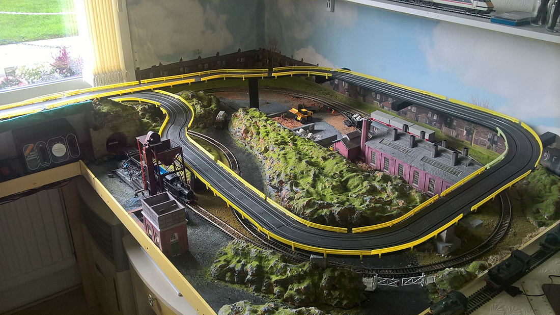
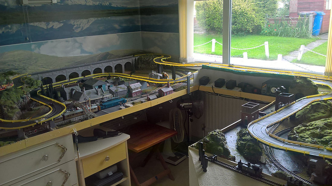
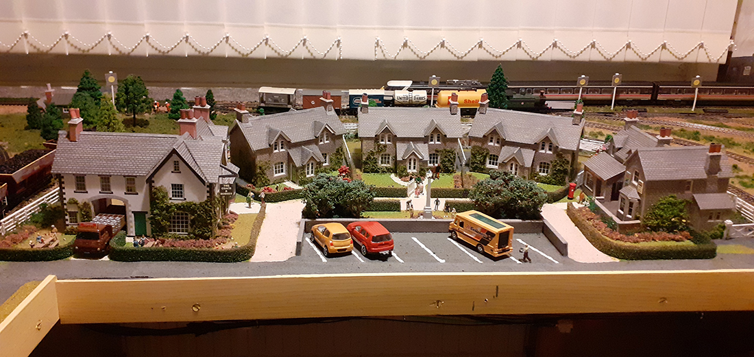
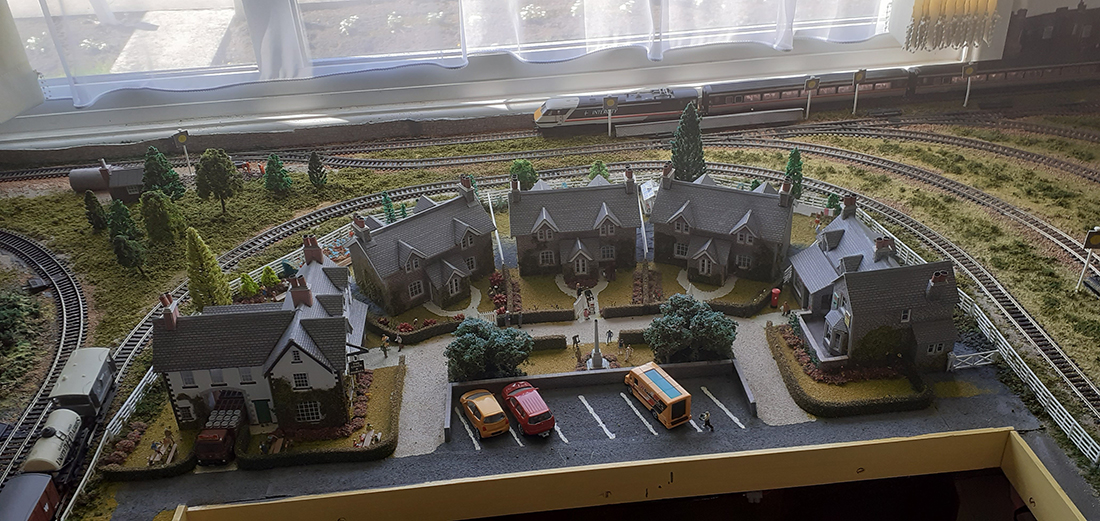
This version is the latest in several built over the last twenty years, is portable and fits easily in my SUV. It measures 2ft 6in by 6ft and comes in two sections that clip together.
Since last year I have been converting all my locos to radio control; quite a challenge considering the size of 009 locos. To date I have completed four. This means I have no problems with track cleaning or electrics. The points (turnouts) are controlled through a ‘wire in tube’ method.
The majority of the structures are scratch built and are based on buildings in or around my village.
The scenic structure uses 5mm foam board which is strong, very light and easy to work with a craft knife. This, where appropriate, is covered with plaster bandage dipped in a dyed water solution to take away the whiteness.
I enjoy the scenic side of the hobby most but have running sessions when the grandchildren come (not since March of course)!
Keith”

A huge thanks to Bob for sharing his terminal strip model train wiring, and to Keith.
Bob frazzled my brain, and Keith put a big smile on my face with that workman scene from the photo. Loved it.
That’s all for today folks.
Please do keep ’em coming.
Don’t forget the Beginner’s Guide is here if you want to join in with the fun.
Best
Al
PS Latest ebay cheat sheet is here