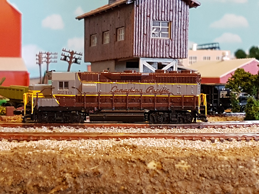
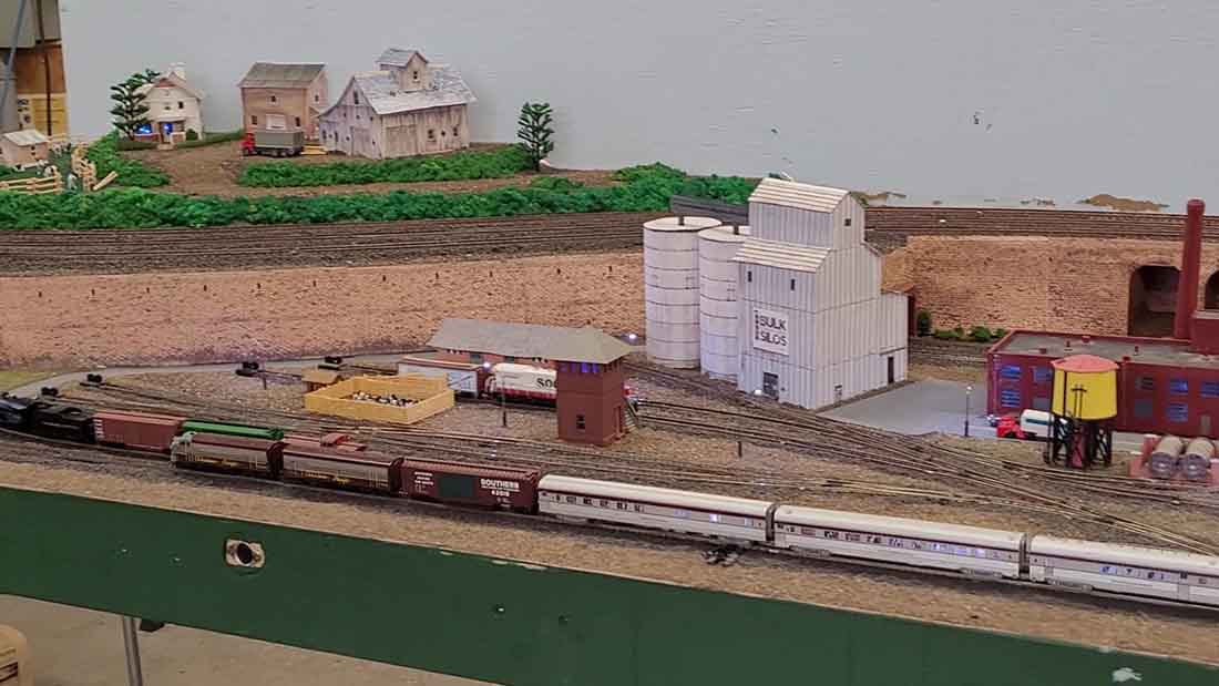
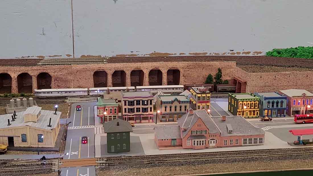
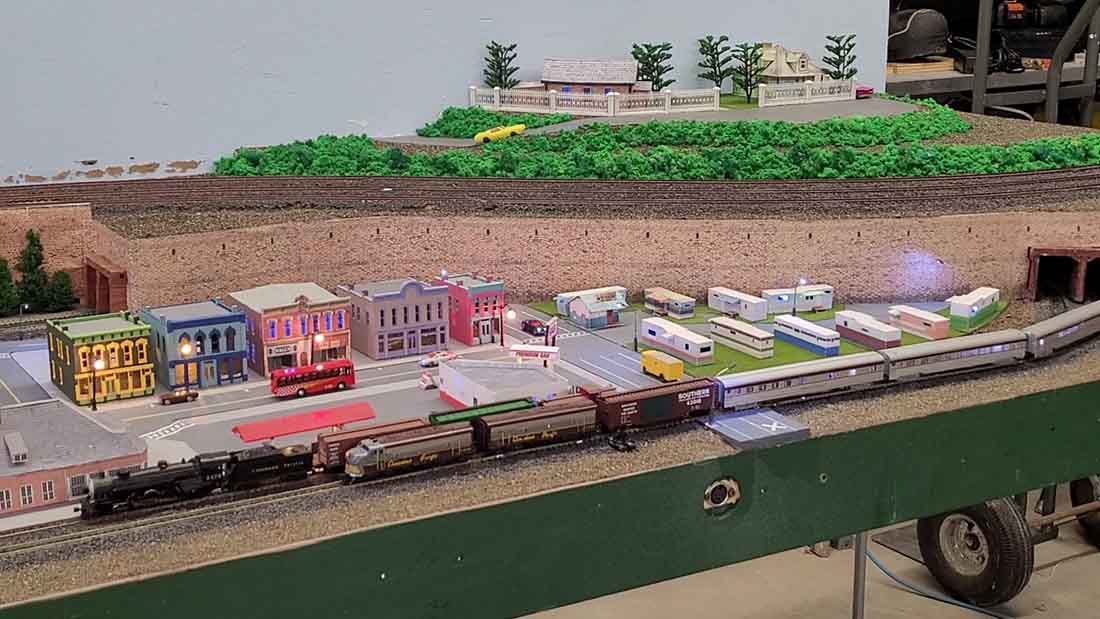
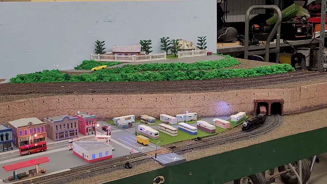
Manny has been in touch with his 5×9 HO scale layout:
“Hi Al
My name is Manny Papagolos. I’m from NH, USA.
I have been following your posts for a few years and I finally found the time to send some photos and a video of my HO layout.
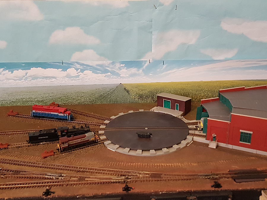
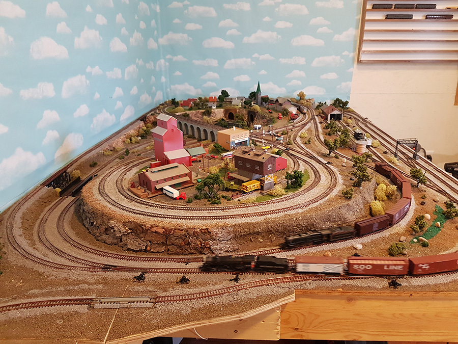
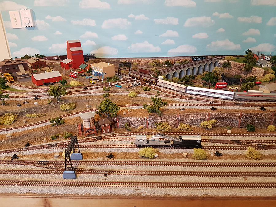
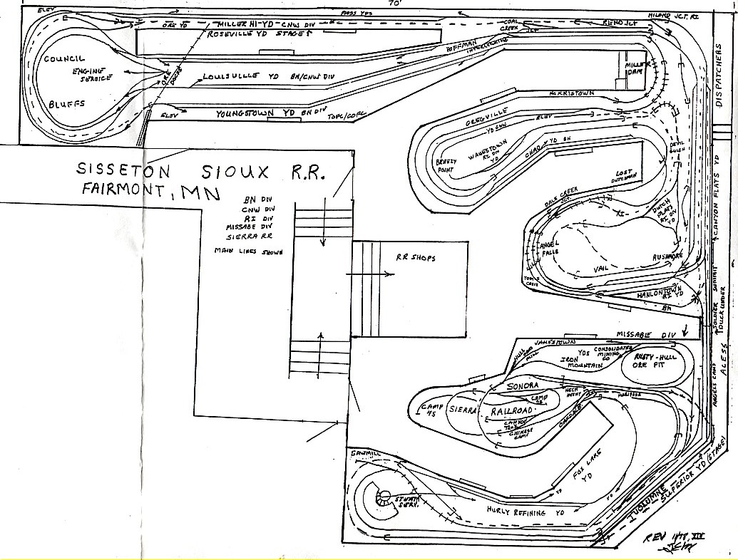
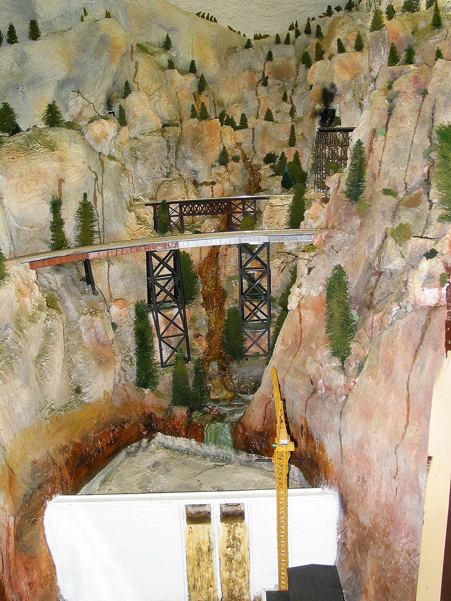
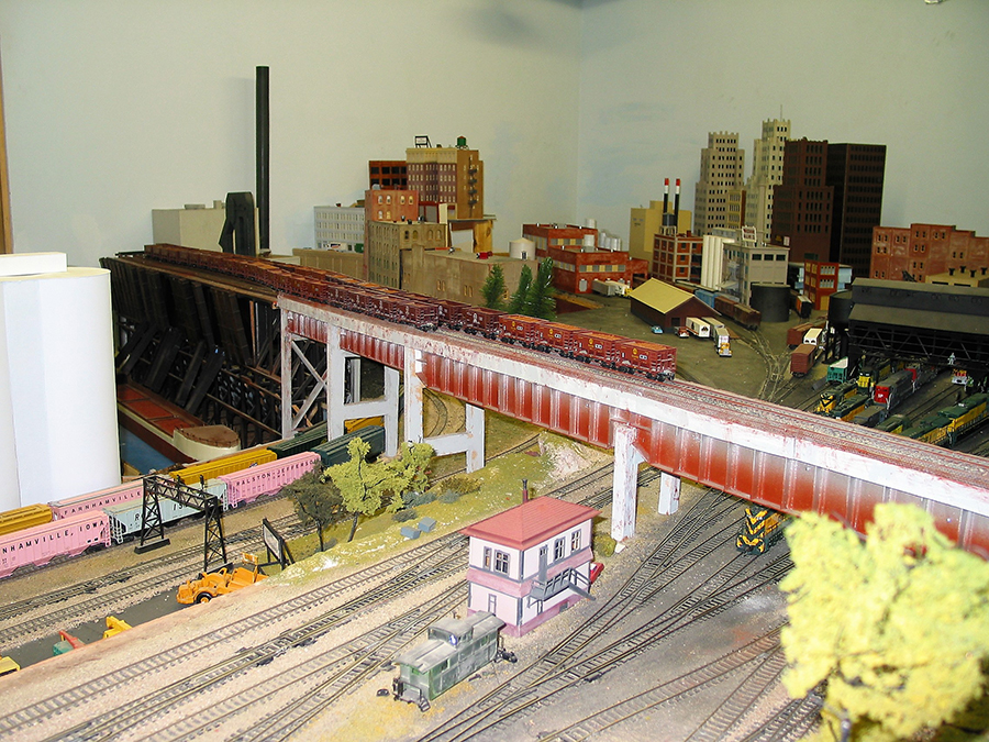
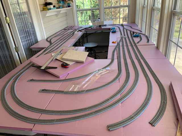
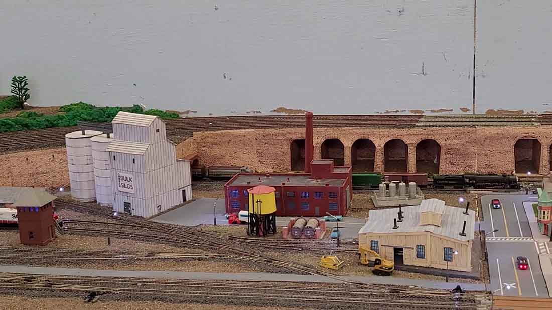
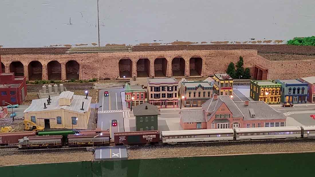
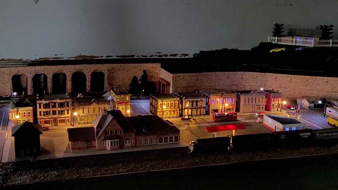
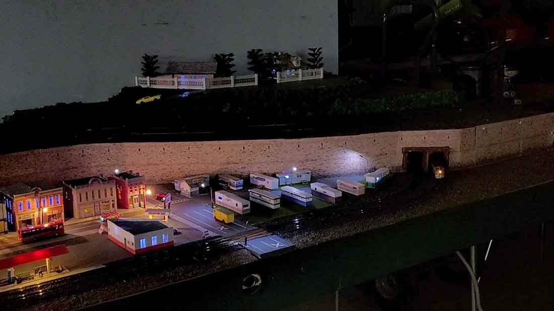
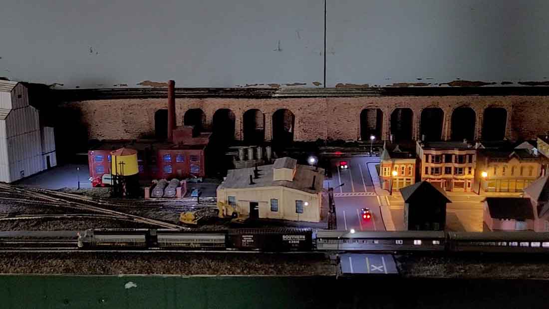
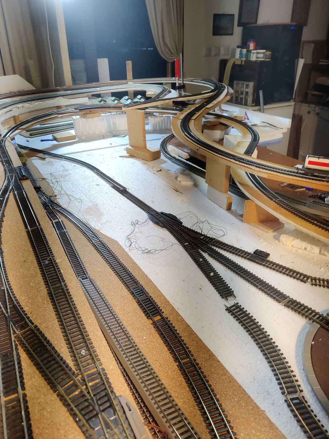
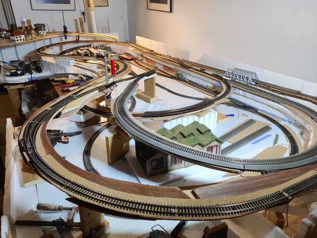
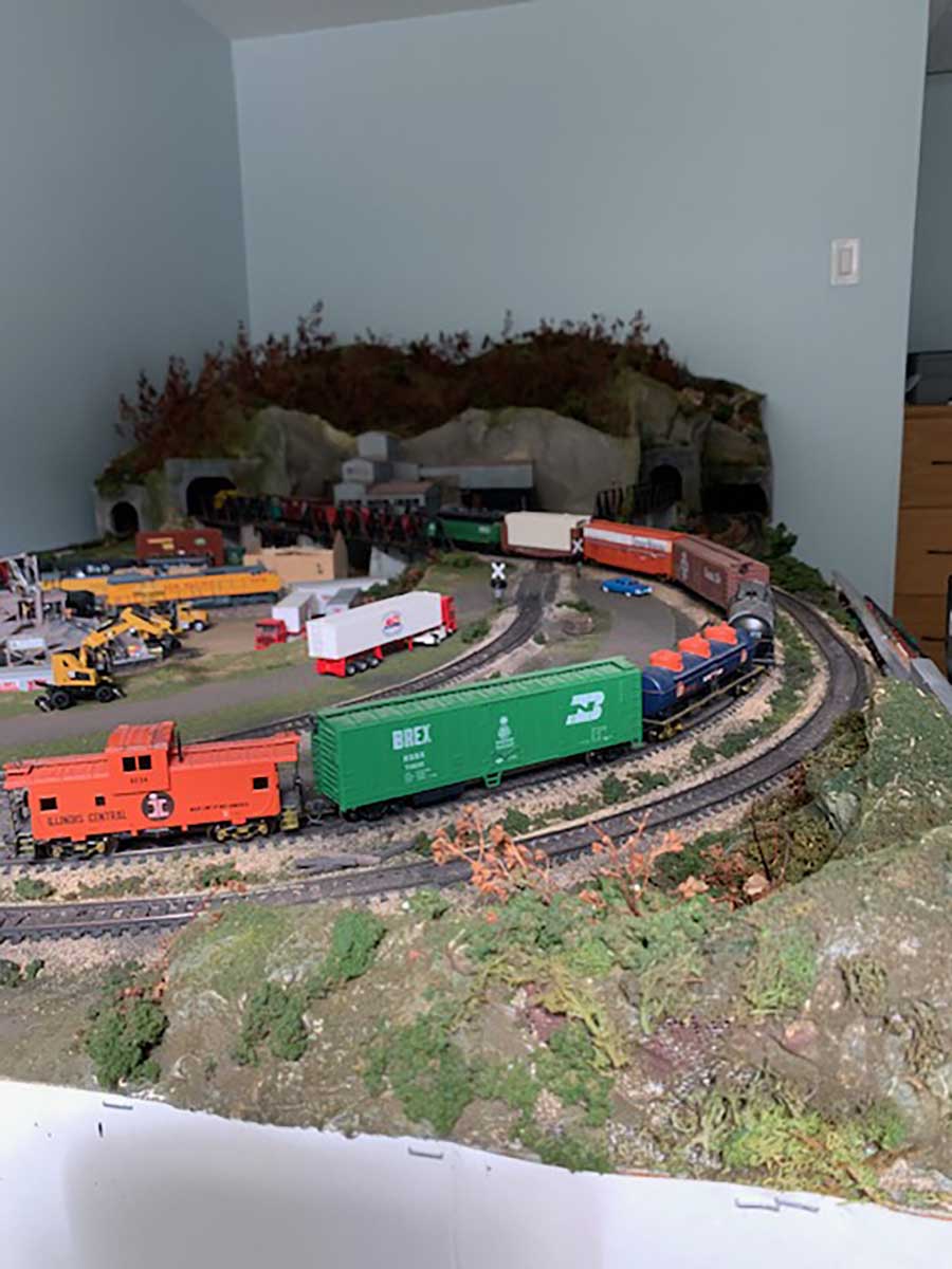
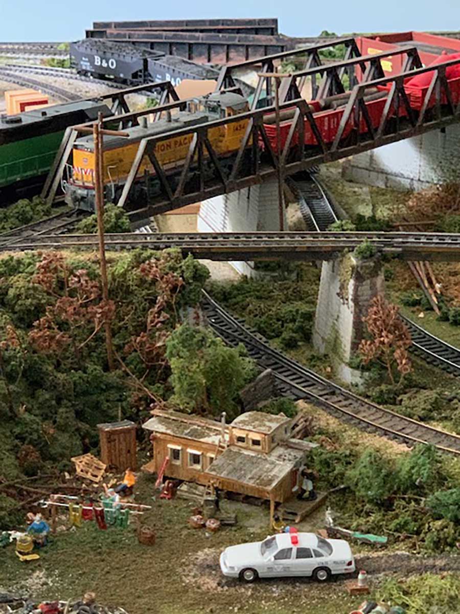
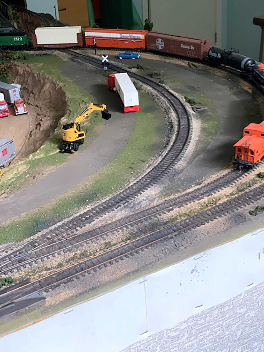
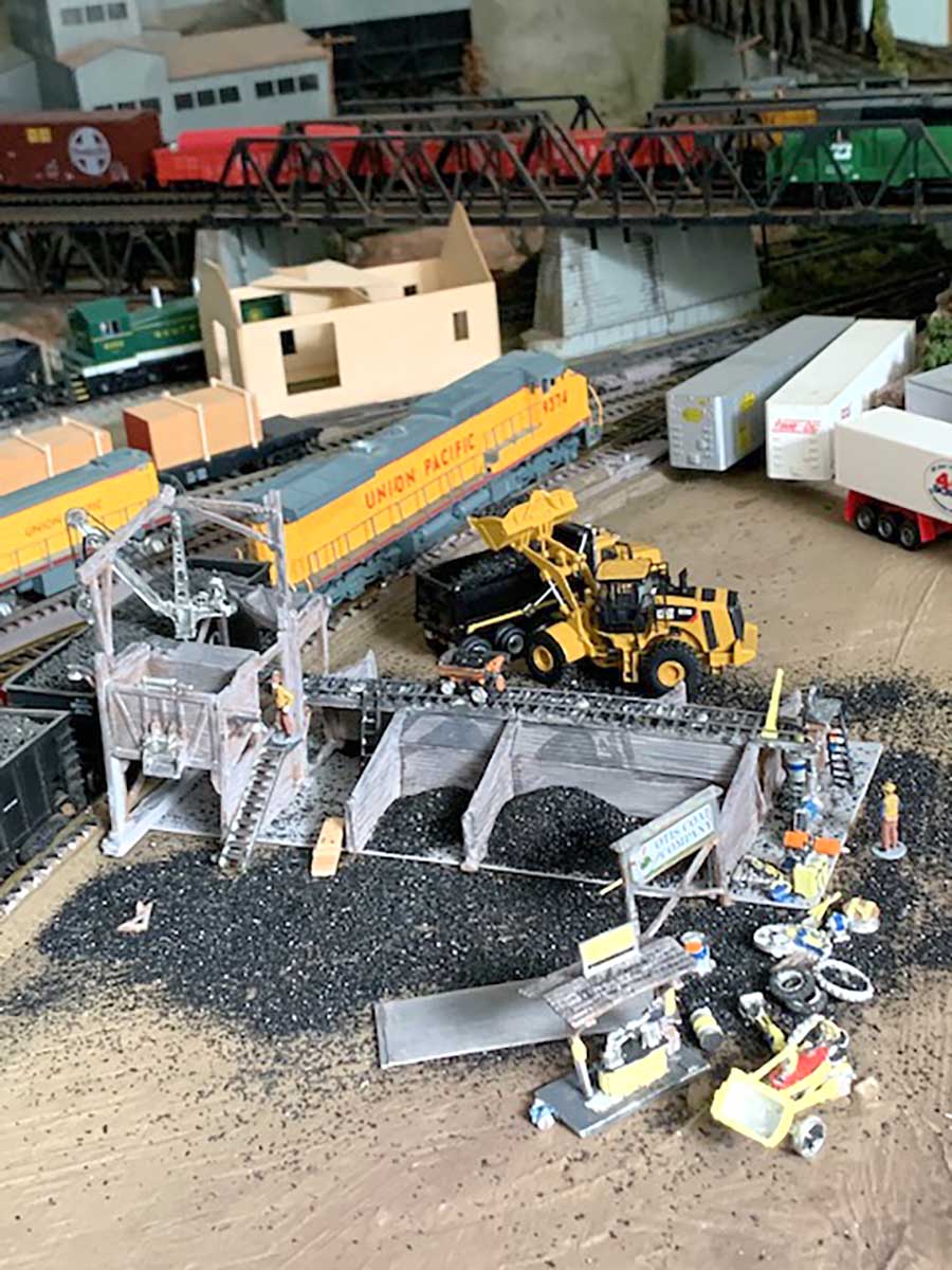
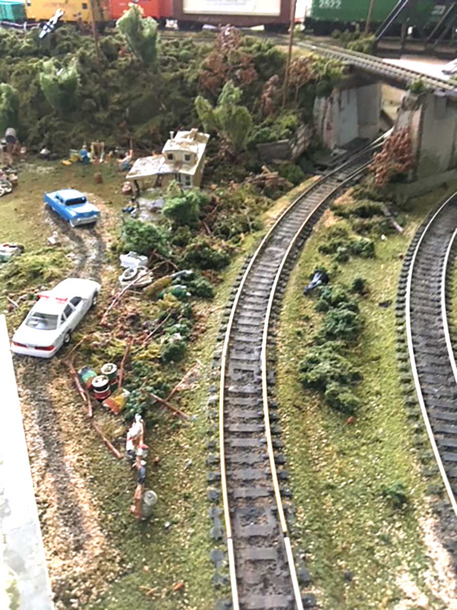
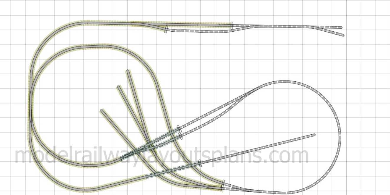
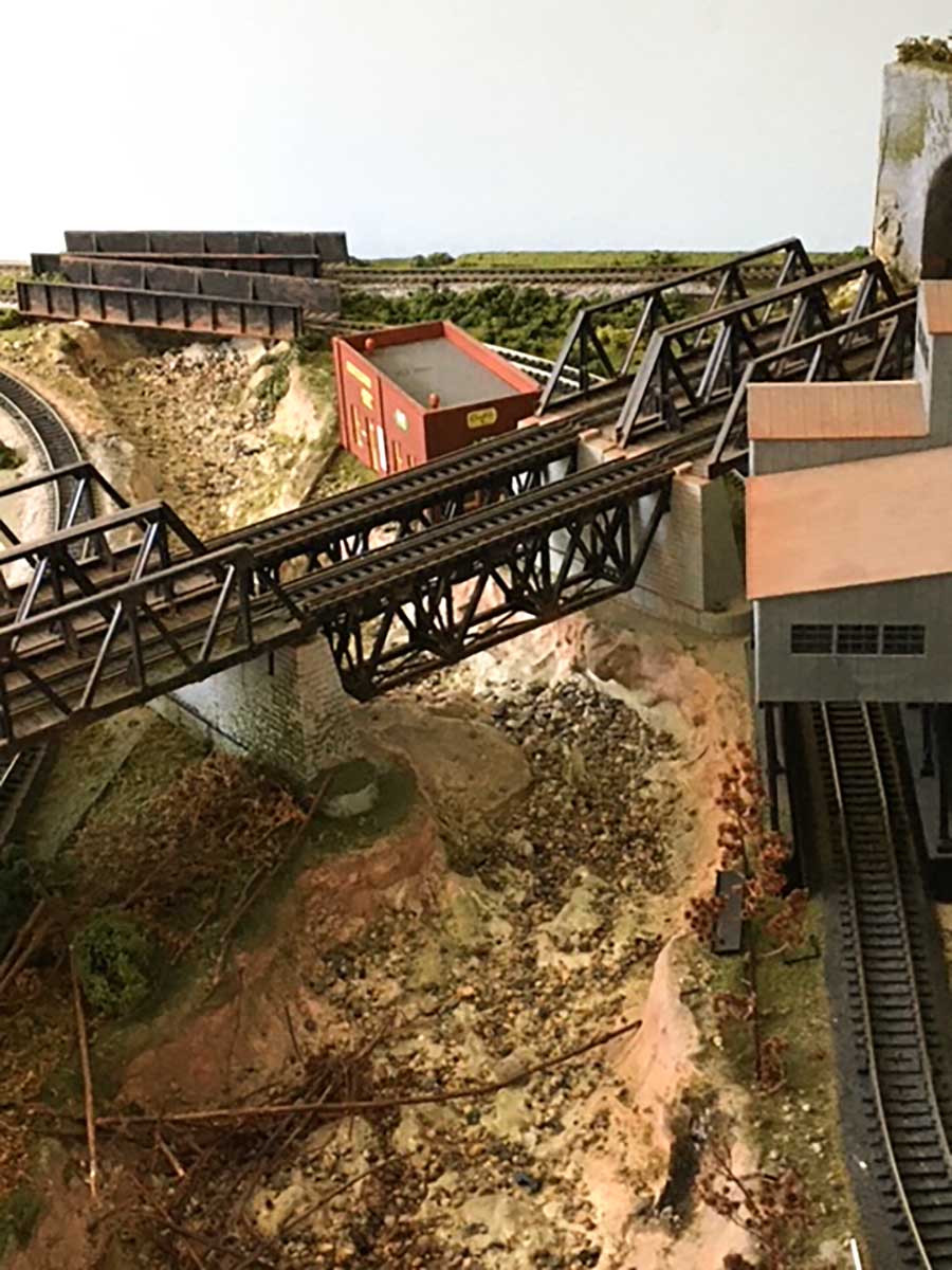
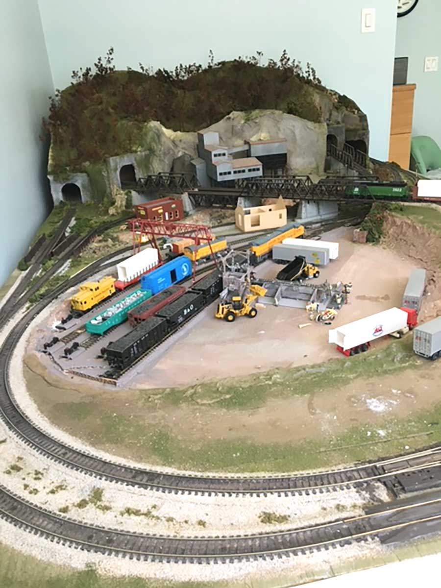
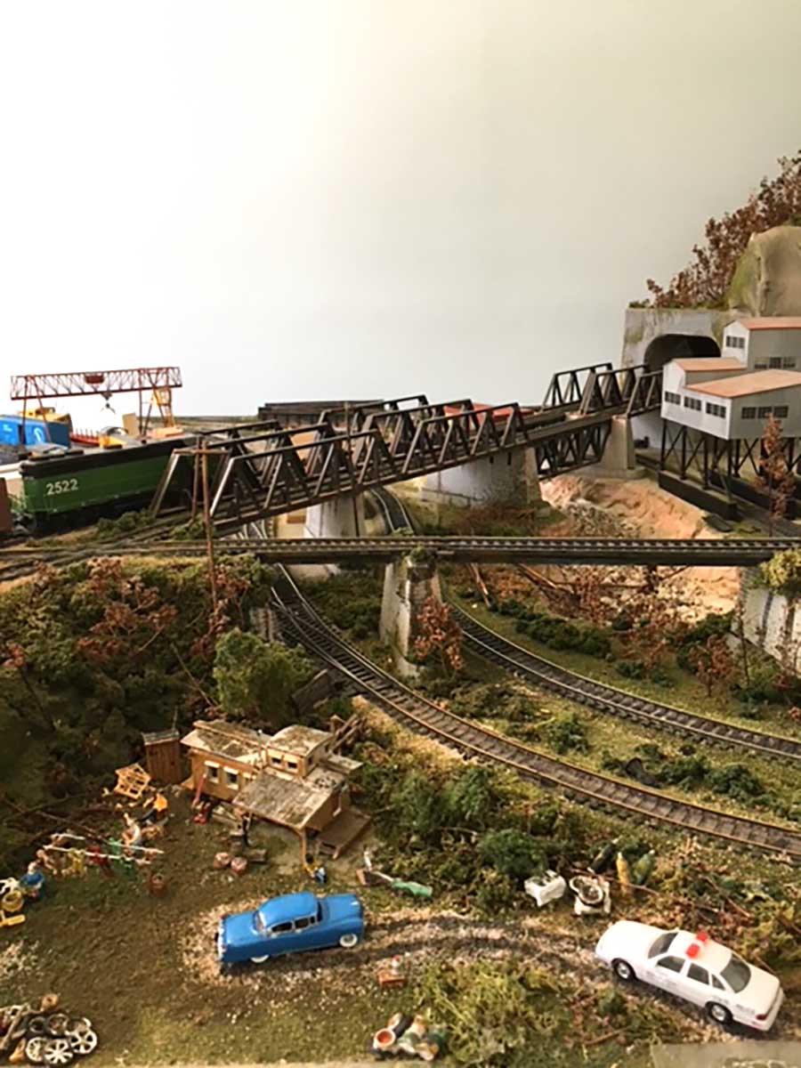
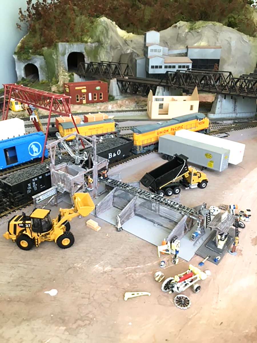
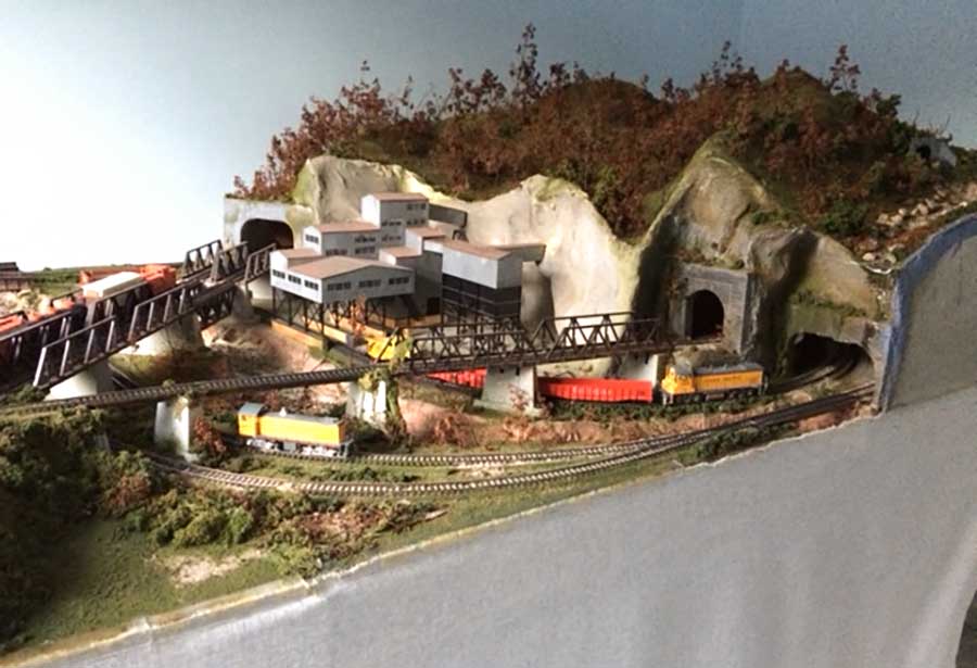
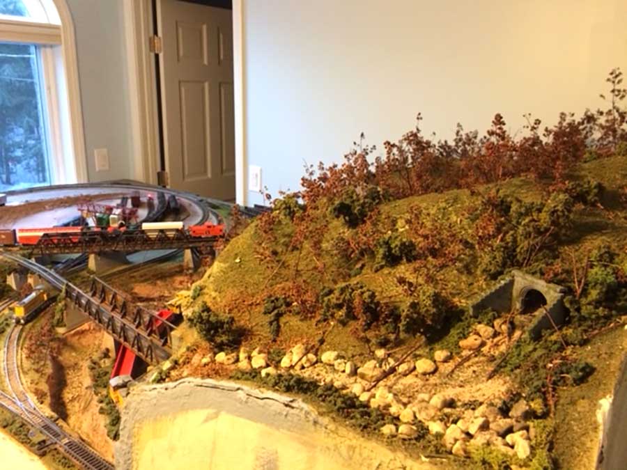
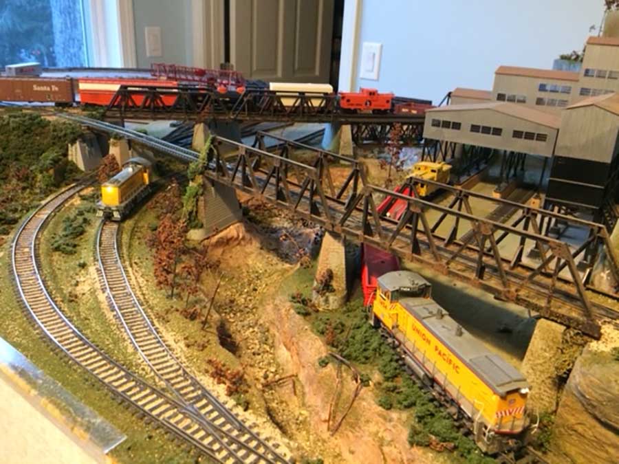
It’s 5ft X 9ft. with the ability to be split in two separate halves 4 1/2ft X 5ft for ease of moving, double figure 8 running through a narrow river gorge with a lot of bridges to get the trains through the mountains, built from an Atlas track book copyright 1958,1971 2nd edition “railroads you can build” I’m sure there will be a few people that recognize it (Granite Gorge & Northern).
I started it in the late 70s and I am still working on it. It’s very enjoyable and inspiring to see what others are doing on their layouts. I would like to thank you and all the others that post for giving us all great ideas and tips.
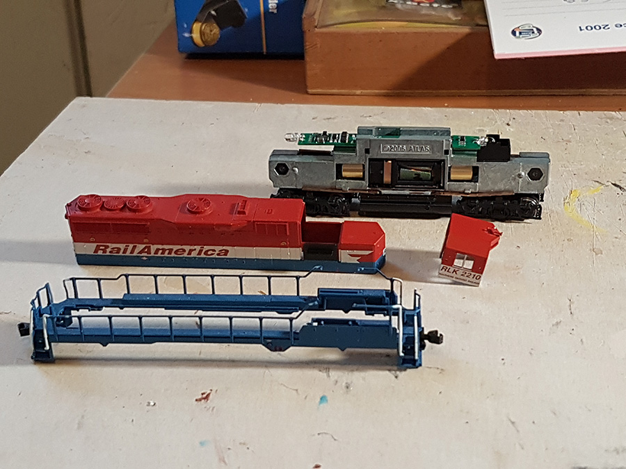
My layout started out as a DC system and has since been changed to DCC NCE 5 amp booster with a wireless control system.
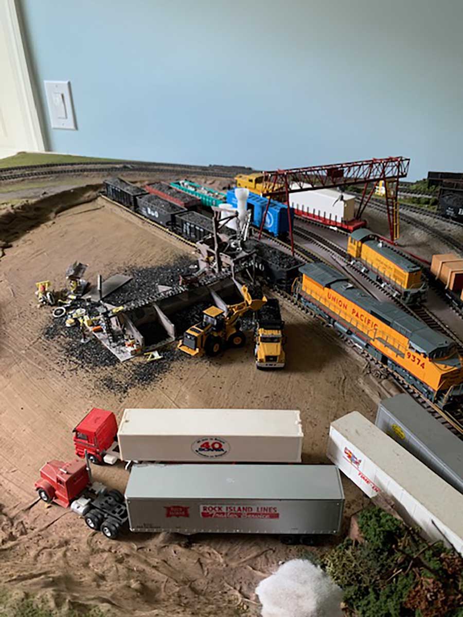
I do not run it as a prototypical railroad. I just enjoy working on it and running it in the winter as I am retired now and have the time and space. So the nice thing about building the layout was that the book gave you cookbook directions so it took out the guesswork engineering to get you started.
As I said, I started in the 70s when my children were young. I now have grandchildren so we do get a lot of enjoyment out of it. One of the drawbacks is it was built with all pieces of Atlas track, I wished I had used flex track to have less joints.
It has a plywood base with a cork road bed. The mountain is made with a cardboard framework with household screening and joint compound. It has access at the rear.
I have placed the layout on 6 caster wheels with a large shelf underneath for storage. The wheels make it easy to move it around to get access to the other two sides.
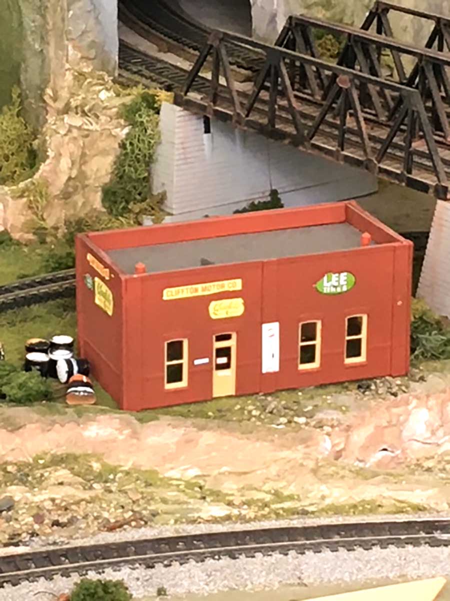
As one can see I still have more work to do.
Manny”
(Here’s the ‘larger’ version on youtube.)
I really enjoyed Manny’s video – it’s a joy to see trains running at slow steady speeds.
A big thanks to Manny for sharing his 5×9 HO scale layout.
(It reminded me of Dana’s: HO scale layout 5×14.
I think it has bags of charm – it’s another simple layout that looks great. You can really tell Manny has enjoyed every second of it.
Please do leave a comment below – I’d love to hear what you think of this figure of eight.
That’s all for today folks but please do keep ’em coming.
And if today is the day you stop dreaming and start doing, just like Manny, the Beginner’s Guide is here.
Best
Al
PS Latest ebay cheat sheet is here.
PPS More HO scale train layouts here if that’s your thing.
Need buildings for your layout? Have a look at the Silly Discount bundle.