You are a daily read and I’ve waited far too long to send you a video of my layout.
Background:
We retired from Colorado to Lake Lanier Georgia in September.
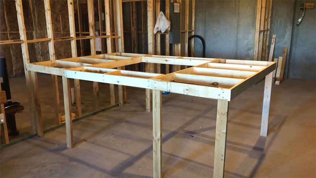
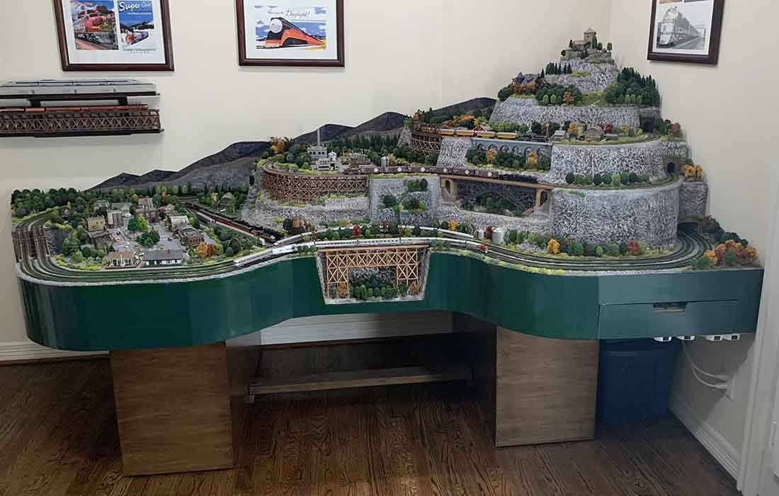
Work began quickly on my new layout, a 6×12 duck under located in our walkout basement.
I was able to recycle so much of my previous layout in Colorado and applied lessons learned from that one to the new one.
Not the least of which is a layout height of 43 inches for easy access to wiring etc under the layout.
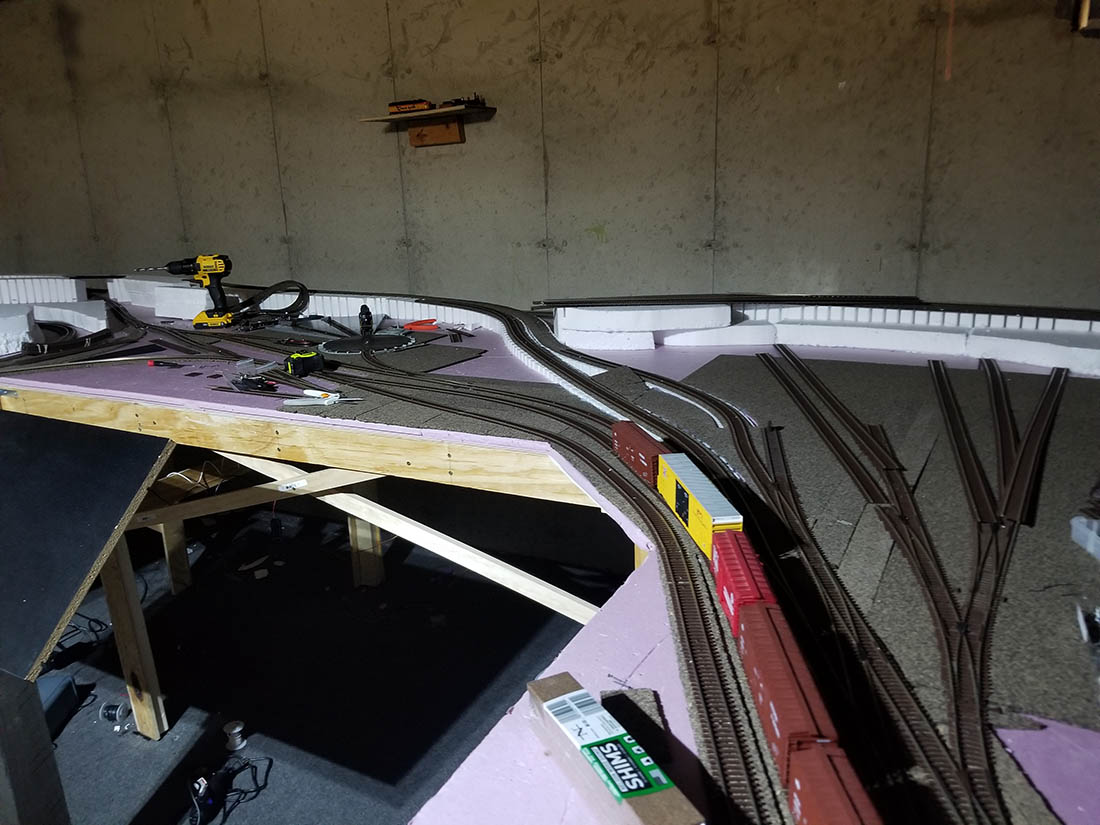
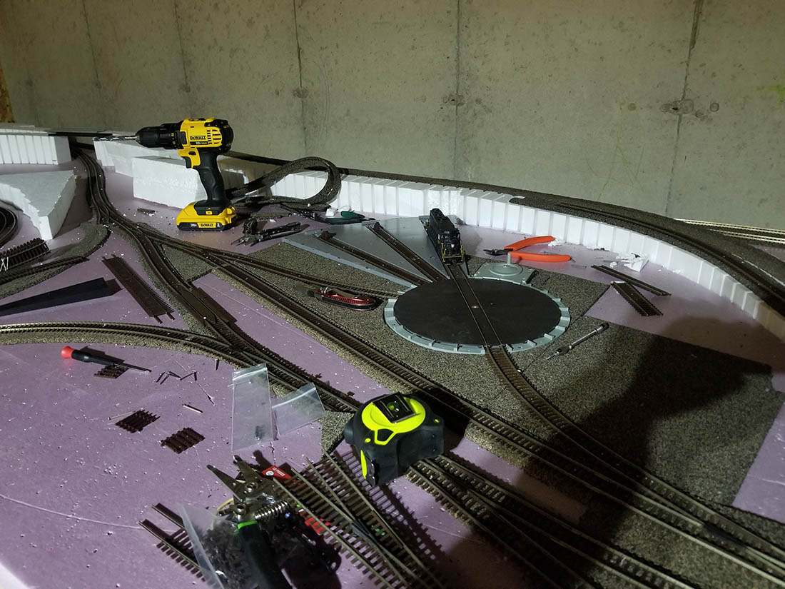
My video shows you a quick look at the initial framing to how the layout looks today.
So, here’s my tour:
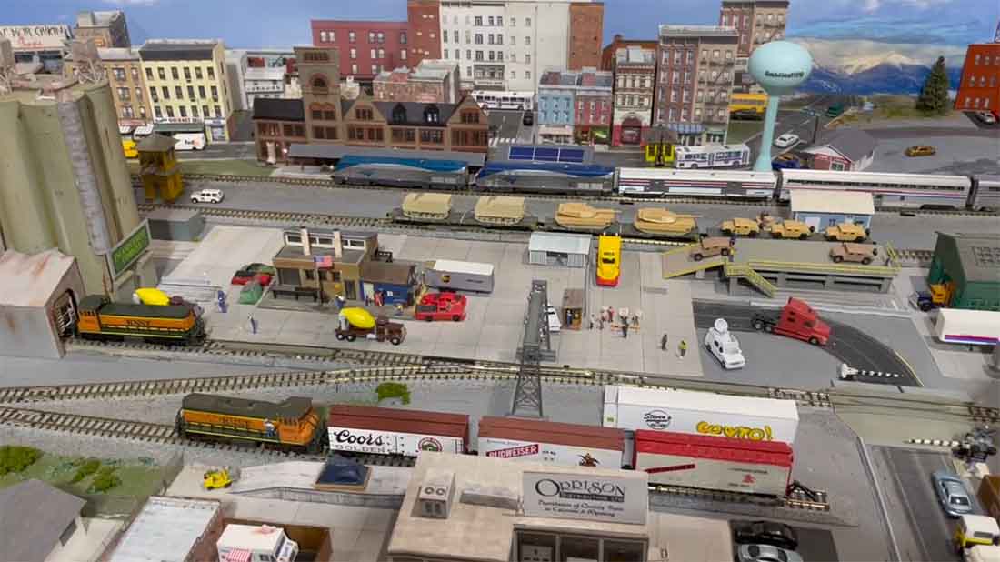
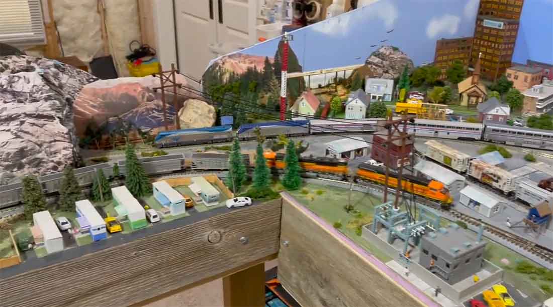
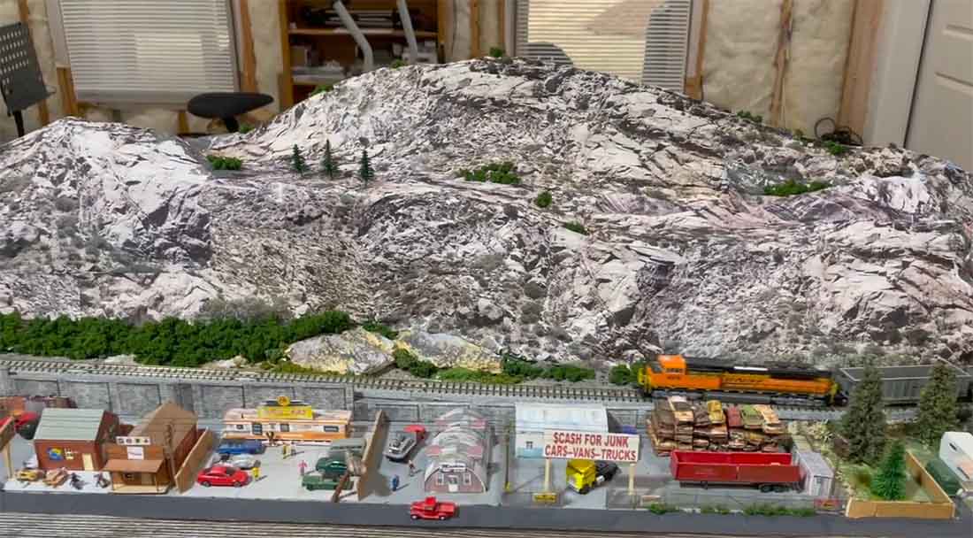
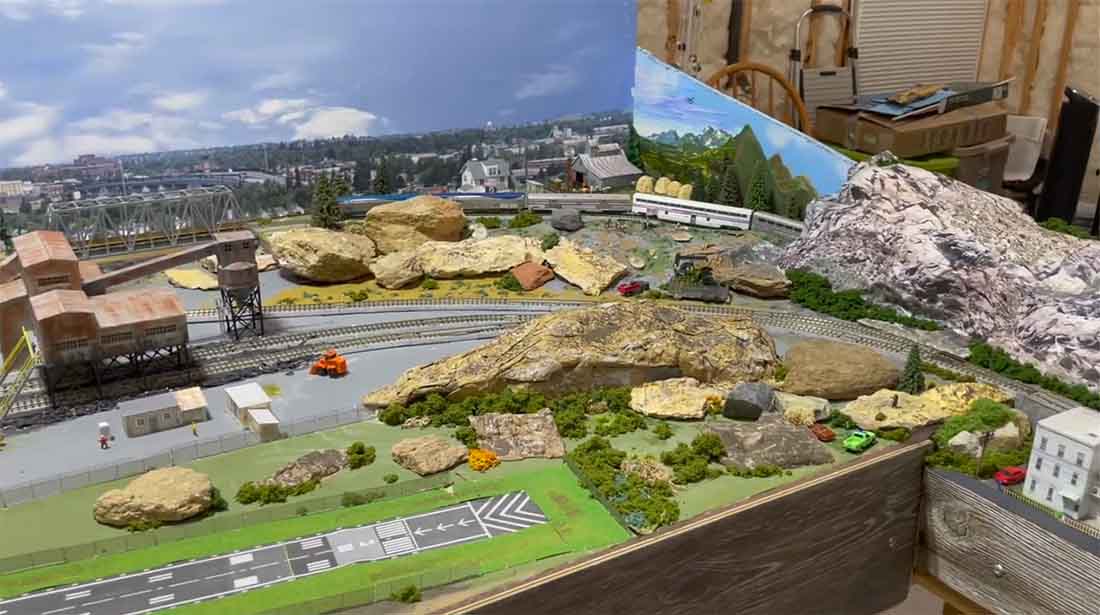
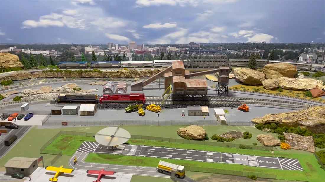
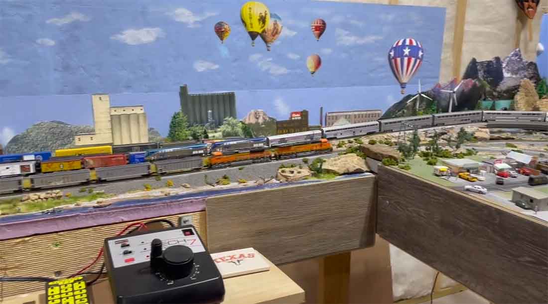
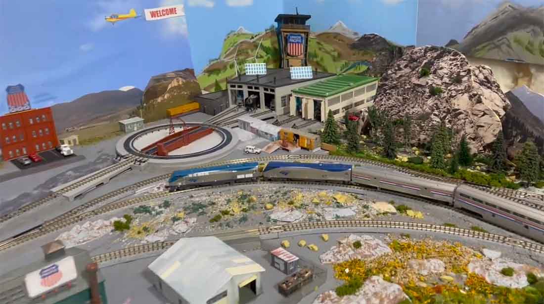
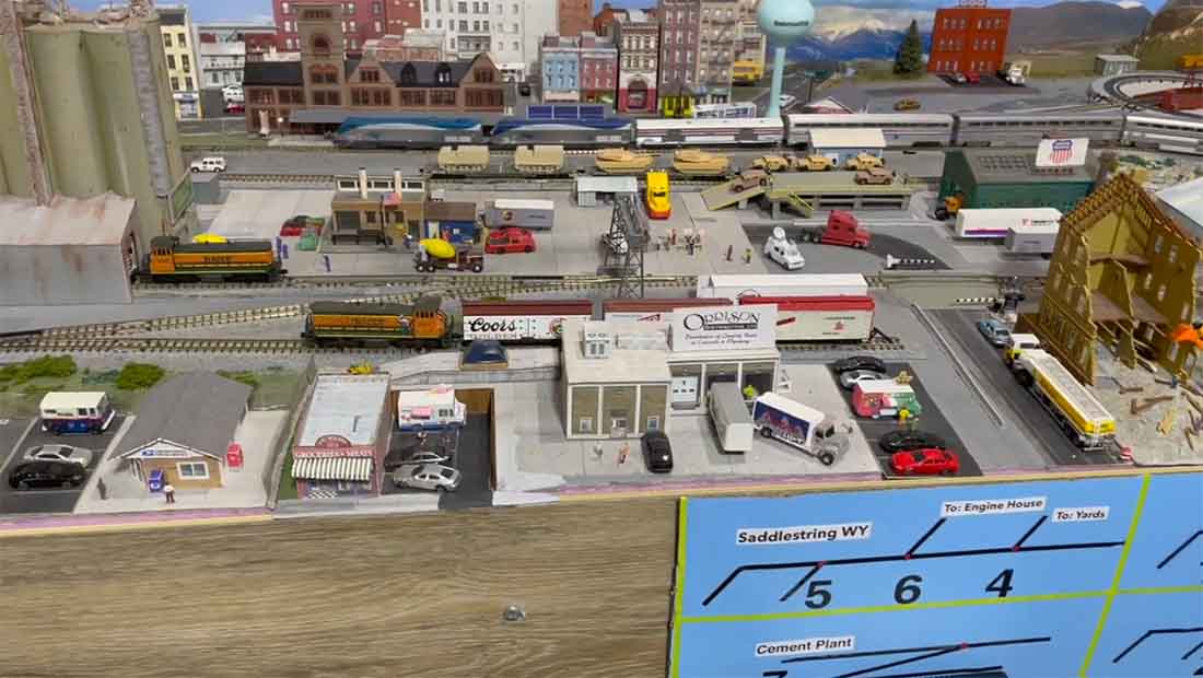
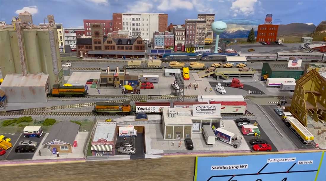
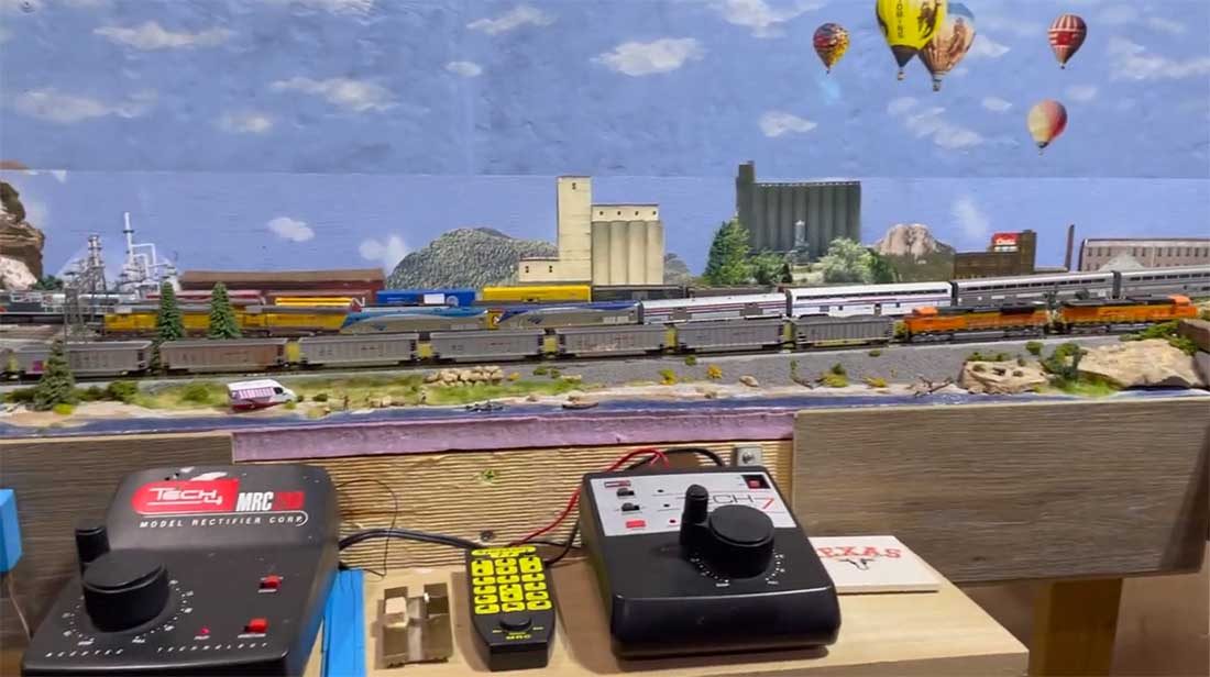
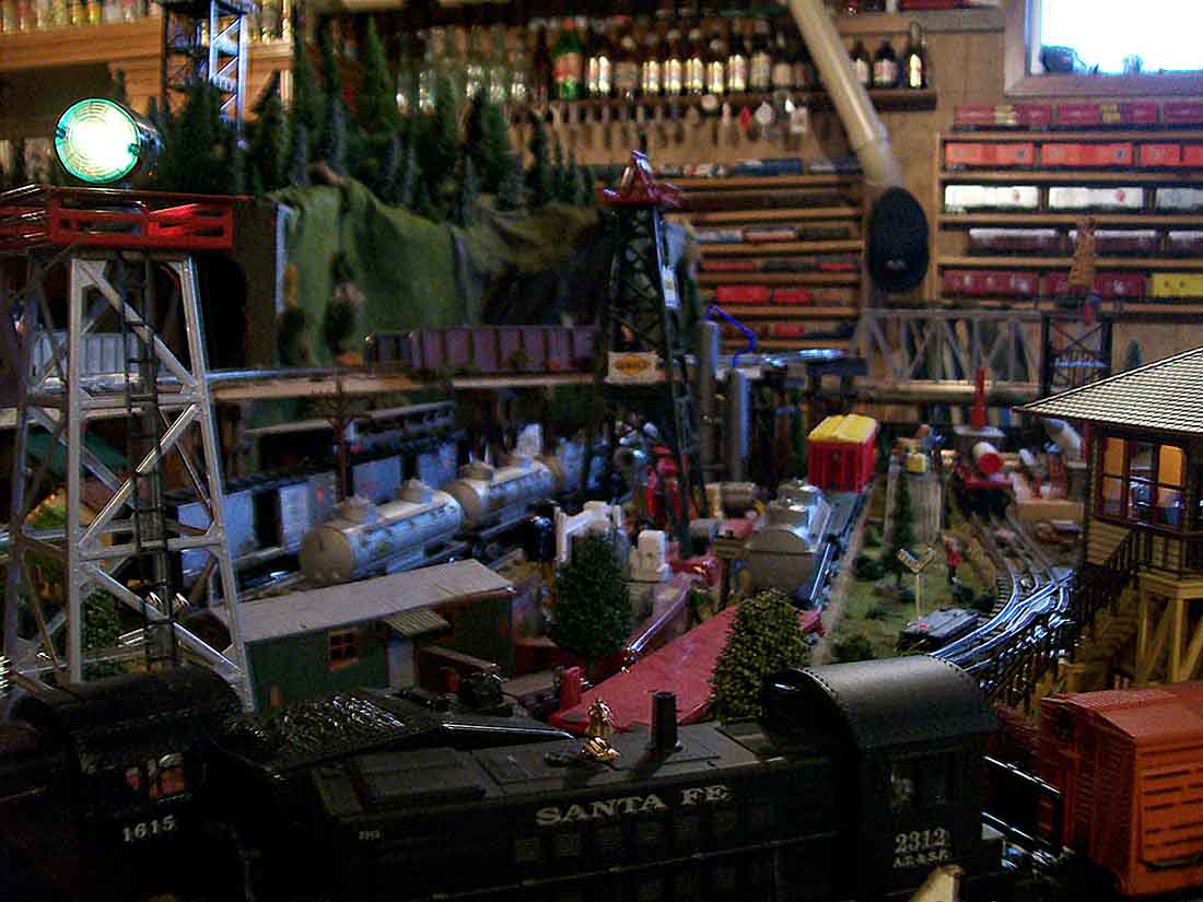
I have two main lines, one for UP/Amtrak and the other for BNSF.
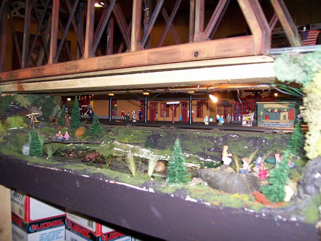
The layout is situated in Wyoming, location based on the best selling series of books by author C.J. Box.
It has lots of “inside” scenes for those who read the popular series.
Power is DC. I can operate two lines at the same time and that’s enough for me. Track and engines are KATO.
Hope you can share with your readers!
Brian Olson
Gainesville GA”
A big thanks to Brian for sharing his 6×12 N scale.
It certainly looks like he’s having fun and that’s what it’s all about.
I read a comment from one of you recently which really struck a chord with me, because there is never one way of doing something – and none of them are wrong.
The comment – I think it was posted by George – simple said:
“If you’re having fun, you’re doing it right.”
Amen to that.
That’s all for today folks.
Please do keep ’em coming – it’s all gone very quiet at the mo.
Well, once I’d connected the dots, I was happy to post:
“Al…I hope all is well with you.
Here is a new post that is a little different but I hope everyone enjoys it.
We model railroad hobbyists love to share our passion. We display our layouts in museums, exhibit them at model railroad shows, and participate in blogs like yours.
Once in a while, a less conventional way to share our love of this amazing hobby presents itself. I have recently had such an opportunity.
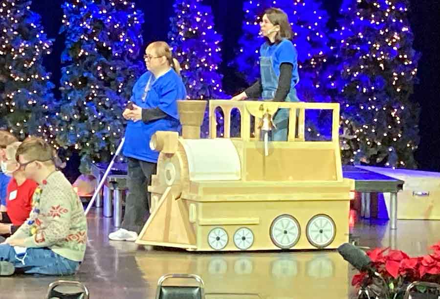
My daughter is the artistic director of a theater program for young adults and adults with a variety of physical and developmental disabilities.
Each year, her clients write and perform in an original musical play. A recurring theme of these musicals is how the actors are often stereotyped by their disabilities and how they are able to overcome these stereotypes.
For the past several years, it has been my privilege to design and build the sets and props for these plays.
This year, the setting for the story was an abandoned amusement park that the actors wanted to restore to its former glory.
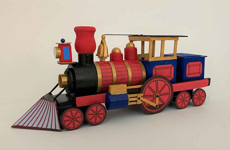
One of the main props needed was a kiddie amusement park train. Their director likes models of the sets and props because it helps her visualize how they will appear on stage.
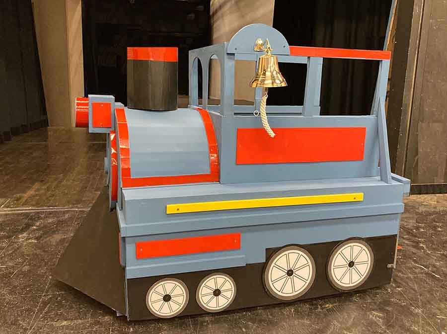
So I make simple models of everything. She did not like the original design for the locomotive because it looked too real.
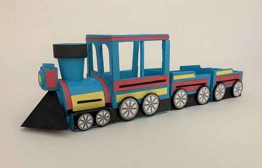
She wanted something that looked more like a kiddie amusement park locomotive. So…back to the drawing board.
The new design met with her approval. She originally wanted a locomotive and two cars; however, because of limited space on the stage, I only constructed the full-scale locomotive.
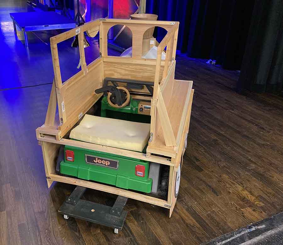
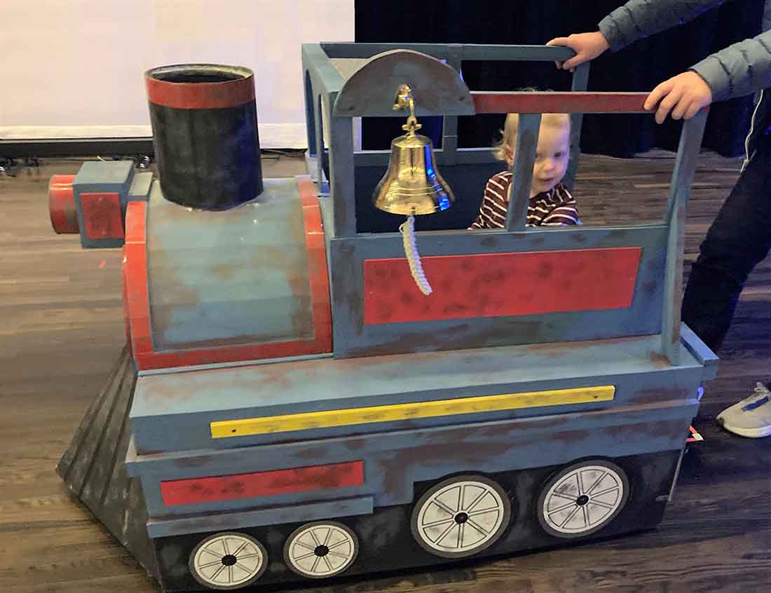
The locomotive had to move under its own power so I fabricated a wooden framework over an electric powered kids ride-on jeep .
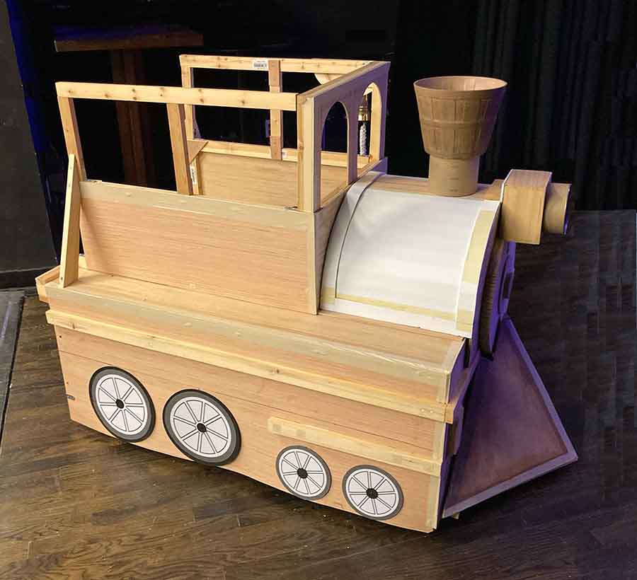
The locomotive body consisted of plywood panels attached to the framework.
The boiler was foamboard and the original smoke stack was a plastic flower pot. The mechanical components typical of a steam locomotive are absent but that is what the director wanted.
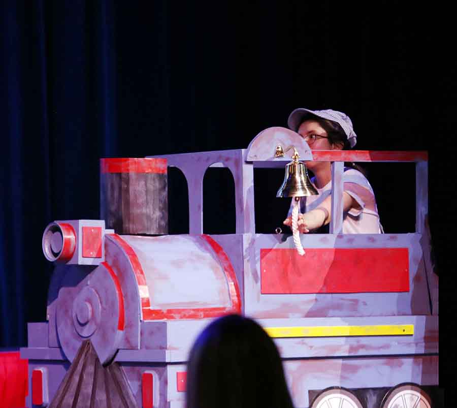
Just before the initial performance, she decided that the locomotive looked entirely too new. After all, it was supposed to be in an abandoned amusement park.
So we did a little last minute weathering.
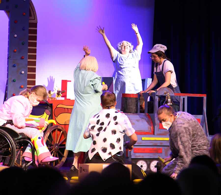
The locomotive’s appearance on stage was greeted with great fanfare.
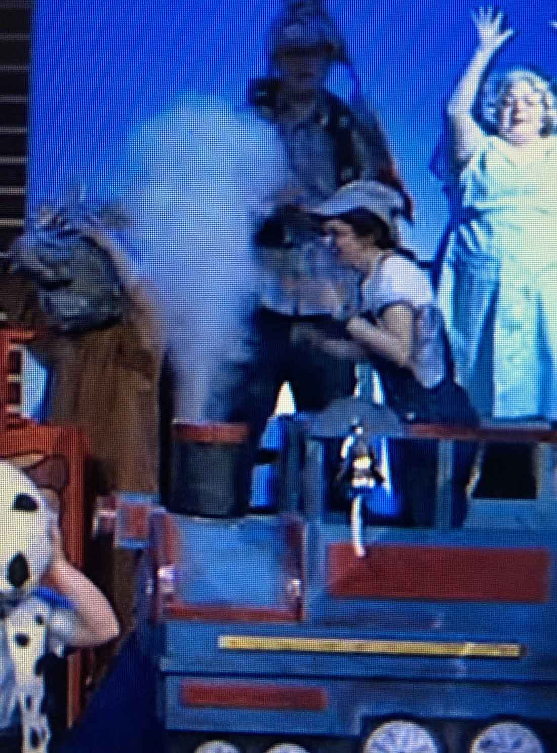
The most challenging part of the build was fabricating a mechanism for blowing a large puff of smoke from the smokestack (now a simple cylinder). The “smoke effect” mechanism consisted of a canister of compressed air and a plastic cup filled with baby power.
I put the mechanism inside the smokestack and a quick pull on the canister trigger released a large plume of baby powder smoke (sorry for the poor quality of the photo…it is a screenshot captured from a video).
The actors, especially the young lad who played the engineer and the audience members loved the smoke. At the end of each performance, children from the audience could have their picture taken sitting in the locomotive.
This was not one of my most mechanically accurate builds but it certainly was one of my most popular.
And…it introduced model railroading to a whole new audience. Thank you for letting me share this with you.
Bob”
That’s all for today folks – please do keep ’em coming because I am emjoy them as much as you.
I thought I’d opine on a subject that is sometimes overlooked as we build our miniature railroad worlds.
My article here is on “focusing” or “guiding” our visitors to a scene.
A little background. In the real world as we visit a park, take a walk in the country, or amble through a museum, most of us will not remember in any detail 90% of the day.
On the way home as we look back at our adventure, we’ll remember specific parts of the day’s journey. Very little or at best most is not pinned to our memory.
So then, what made the memory flashbulb go off? The scene had something to draw our eye and hold it long enough to imprint a memory. Museums are expert at this, we don’t remember the hallway to the dinosaur bones, but remember the bones.
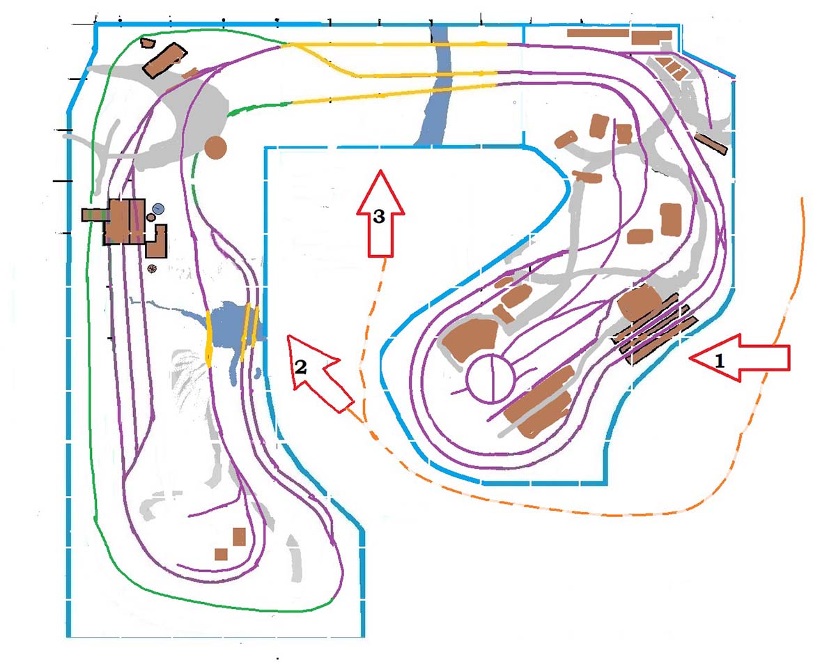
On my layout, I’ve tried to have 3 places where my visitors “take in a scene” as shown in the schematic picture.
In model building we often take great pride in the details of the model, place it on the layout and then have to mention those detail labors of love to our visitors as they are drawn to looking elsewhere.
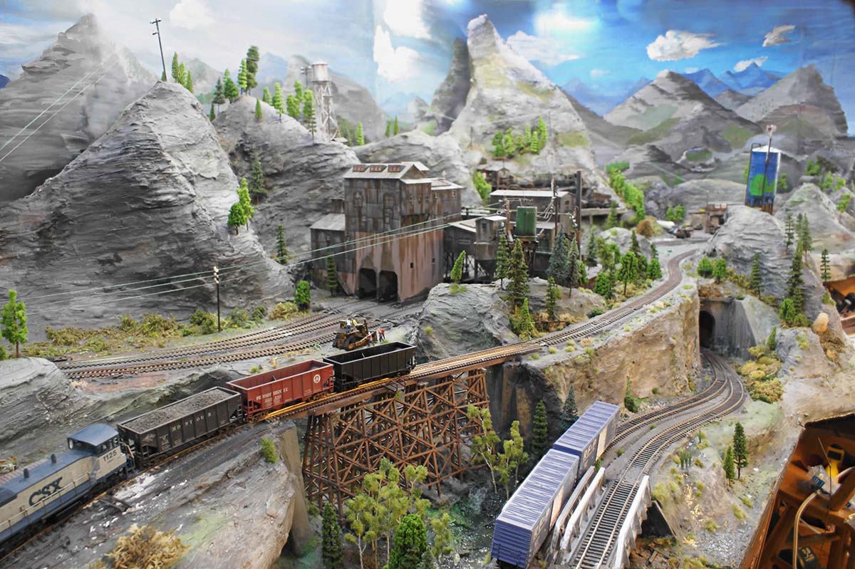
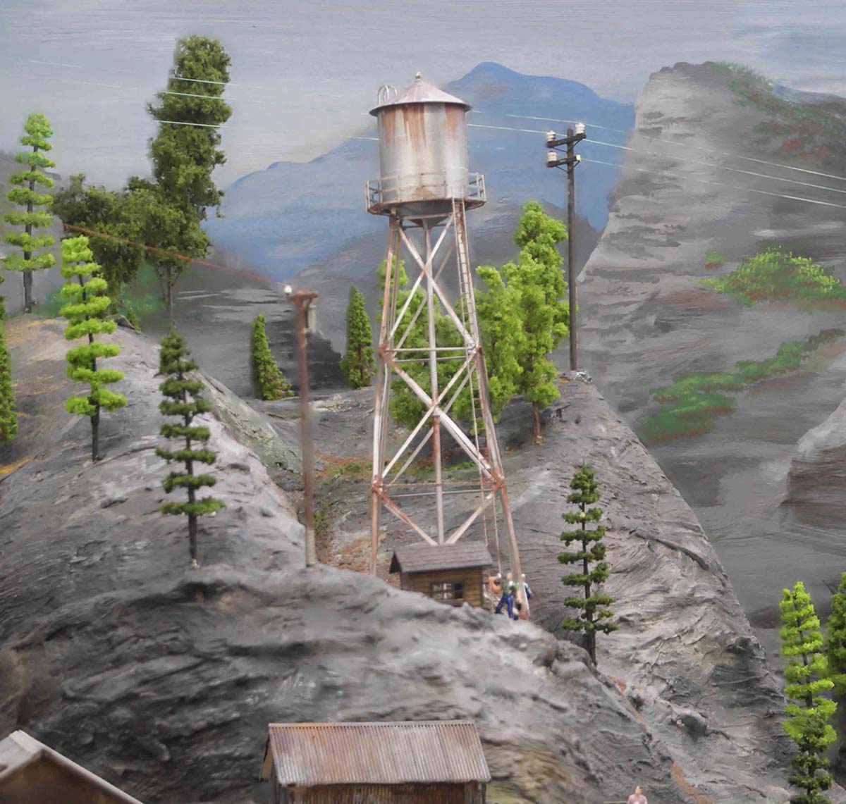
In the pictures I have attached, I have taken from the perspective of the persons visiting my West Virginia mountains, and try to show how I’ve worked to stage the scenes.
Obviously since we are looking at the HO world from what would be equivalent to a helicopter window flying some 500 feet or more in the air, one will see a larger scene than if we were walking along the road in the real world.
That means some manipulation of space is required. I try to present the whole scene, then as one gets closer, mini-scenes of the total.
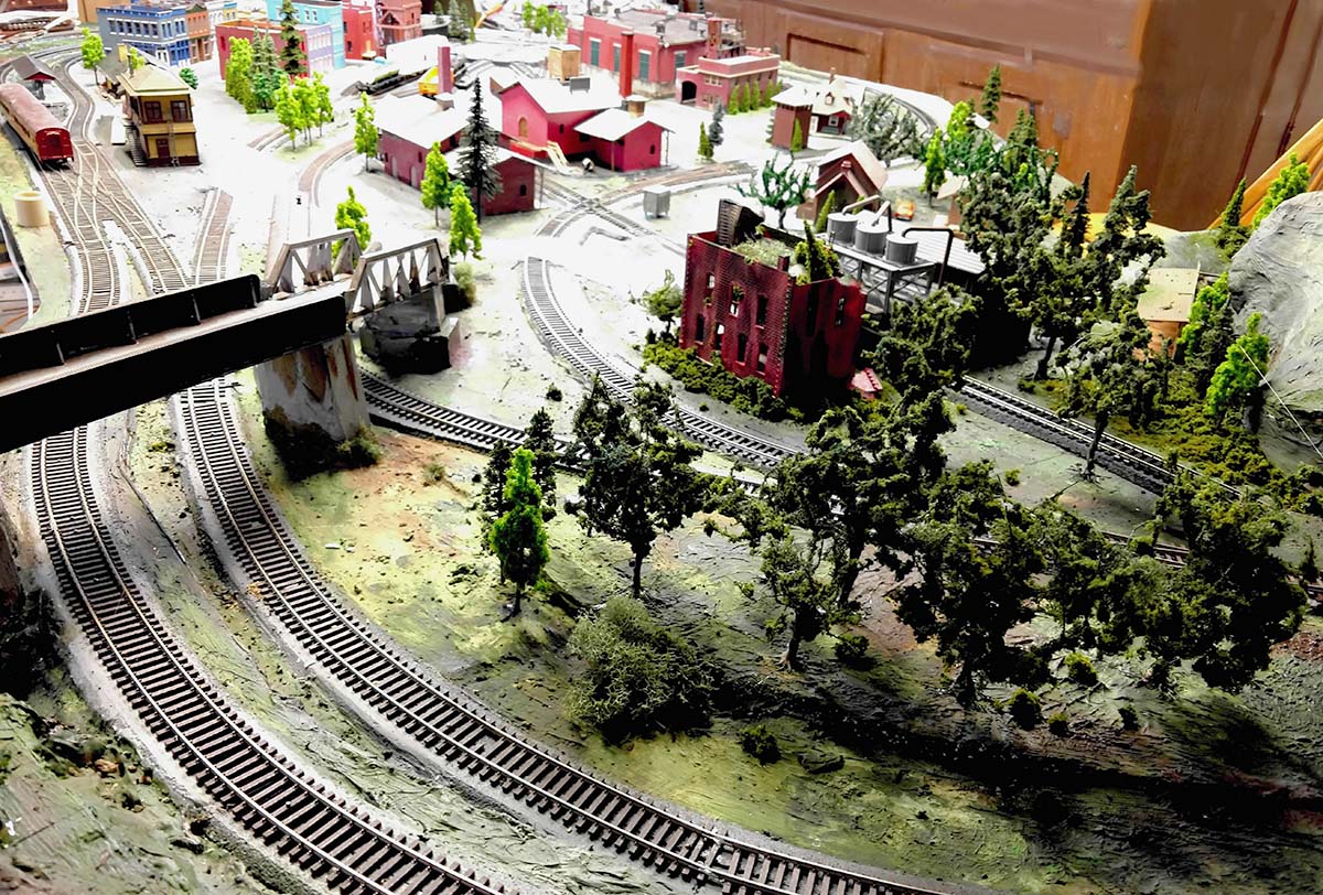
If my visitors are interested in details, such as in the “old mine” picture, I try to have some holes in the trees or places to look past the building to see those details. In the case of the old mine, I made a “funnel” in the hills to draw the eye past the new mine to the old one.
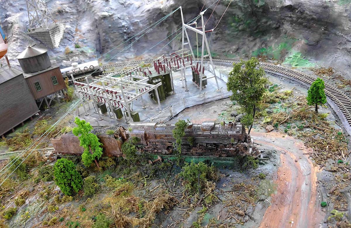
If I want to create focus, and I can, I provide extra light on a place, as shown by example the picture of my electrical sub-station.
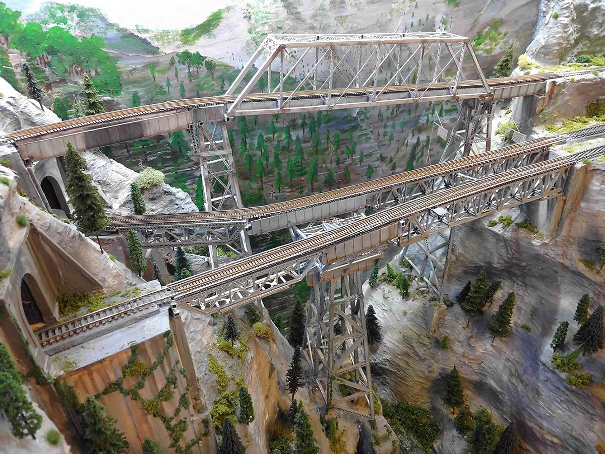
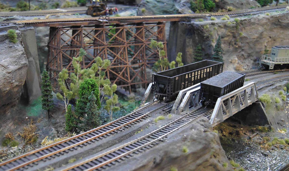
Since I’m modeling mountains in the coal mine sections, I have the advantage of adding details on levels. The picture of the old water tower above the mines supplying water to them is an example of elevating the scene to a different level, as is the picture of wooden bridge which is lower and more in the foreground. Going from eye level and continuing downward, I modeled a canyon under the bridges which drops to just 3” above the floor.
Most of what I have here has been sent in before in articles Al has been kind enough to post, but I thought I’d try to add a new perspective to what we do as we build our models.
I’m happy with the way this layout came out… but some of the radius of the turns are too tight, so I can’t run many of the locomotives and passenger equipment I’d like to have as part of the running environment.
So I’ve been slowing down on “new” construction as I’m going to be moving the layout to a new location. (groan) Starting in a month or so, I’ll be sawing the thing into pieces which I can move from the basement of the house to the top floor attic, some 3 floors (and 5 doorways!) up.
First job is to finish the upstairs room, put down a new floor, get lighting and power where I need it, paint walls and ceiling for background, and add some baseboard heat.
I hope to document the work on what will be very likely my last layout!
“I have been at this 20×16 layout for almost a year now and i think i finally got the first layer done.
I dont have a “plan” i just know what i want in my head.
My first layout was 4×8 and i realized that for HO this was way to small for everything i wanted and to incorporate the things my dad and i wanted to add to his layout when i was a tadpole.
2 mains lines merge to 1 in the what will be the country, a few sides and a lil train watching and switching, has a bit of everything i guess.
I am from Baraboo WI so the Barnum and bailey circus is in my veins and as a little kid, every day i seen the circus train.
One town over North Freedom has a RR museum and you can ride the old steams, in my mind how can you not love trains lol.
After double the size of my old layout this one seems small too, just never enough room for my imagination.
John”
Now on to Robert, who has sent in a good piece on something I’m always going on about: making a start.
“I have been working on a humble N gauge layout that serves two purposes.
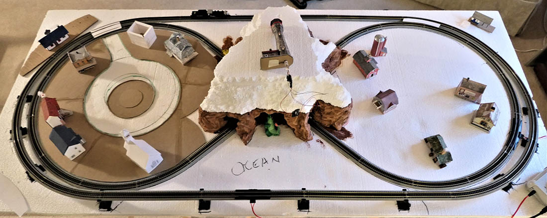
It puts a train around our little Christmas tree, and the rest of the year there’s a mountain in the center with a lighthouse on top for the grandkids to amuse themselves with when they visit.
The whole thing sits atop my stereo cabinet. The layout had to be compact and lightweight.
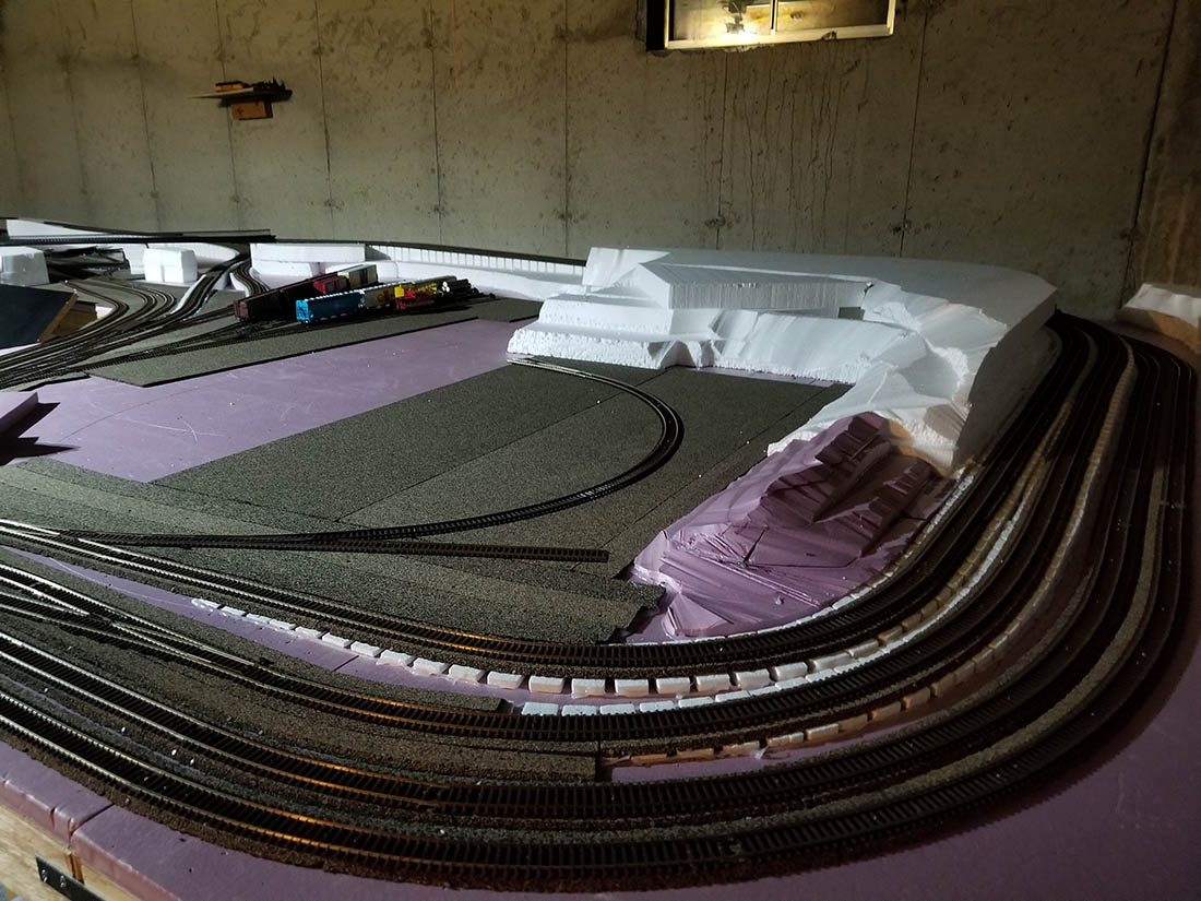
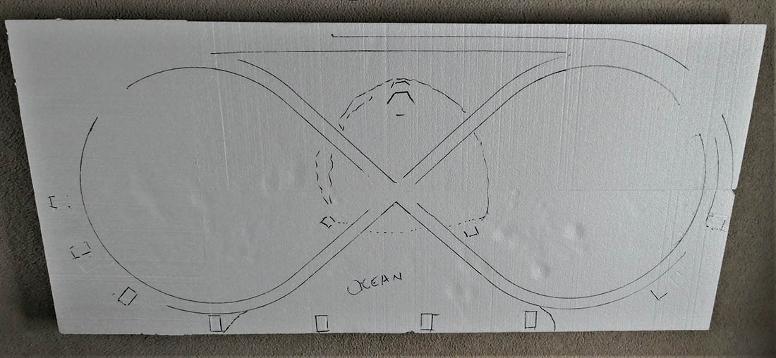
1. I started with Styrofoam insulation sheets. I used low-temperature hot melt along the edges to fuse the sheets. The finished foam base is about 2.5 by 5 feet. I outlined where the tracks would fall and sketched the position of the mountain. The inside track is a figure eight, and the outside is an oval with a trestle in front.
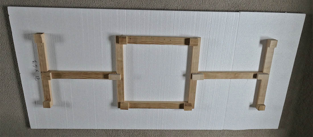
2. I braced the Styrofoam with furring strips and added squares of furring strips as standoffs to provide space for wiring.
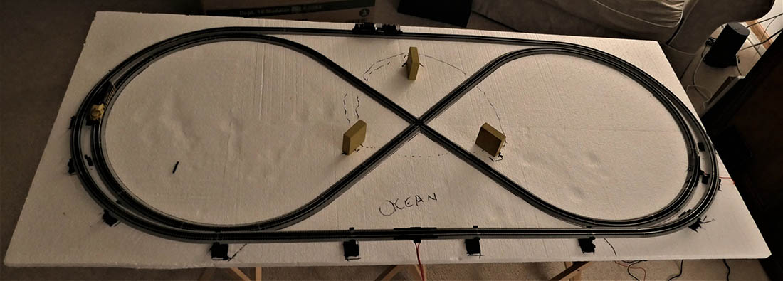
3. Next, I laid the track down, proved it with the trains, made adjustments, then glued it down using Loctite Power Grab construction adhesive. The three blocks in the center serve to hold the Christmas tree legs. They also serve to define the outside shape of the mountain.
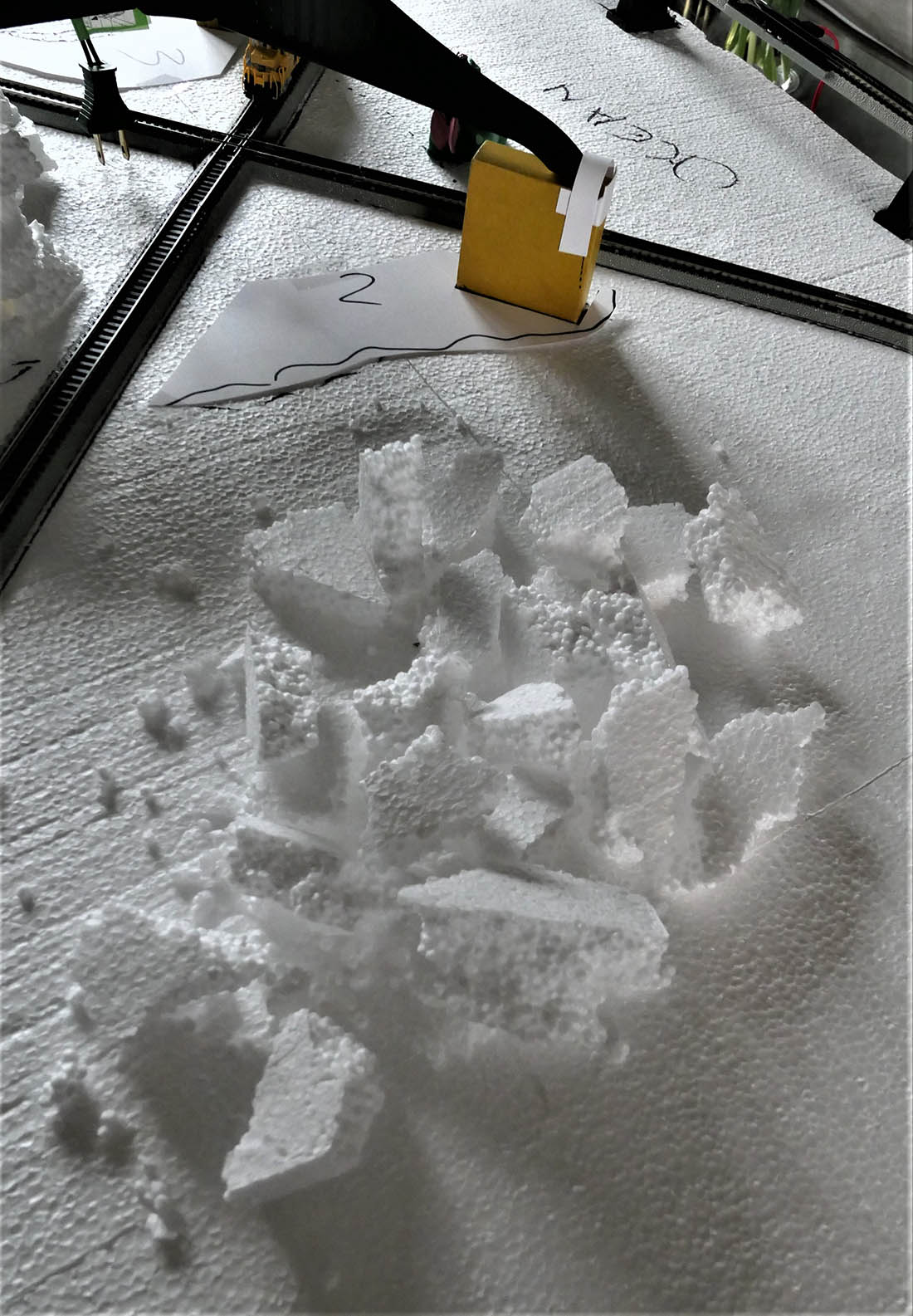
4. I outlined the shape of the walls of the mountain on cardstock, then broke up chunks of Styrofoam and used them like building blocks, gluing them with hotmelt on top of the cardstock outline. Notice the shoe I made from cardstock to hold the foot of the tree. I did this for two of the three legs.
5. Here you can see a partially completed wall. I numbered each of the wall outlines so I would not confuse where each one went. I then sculpted the wall with a razor blade and covered it with tissue and diluted white glue to make it appear more like rock.
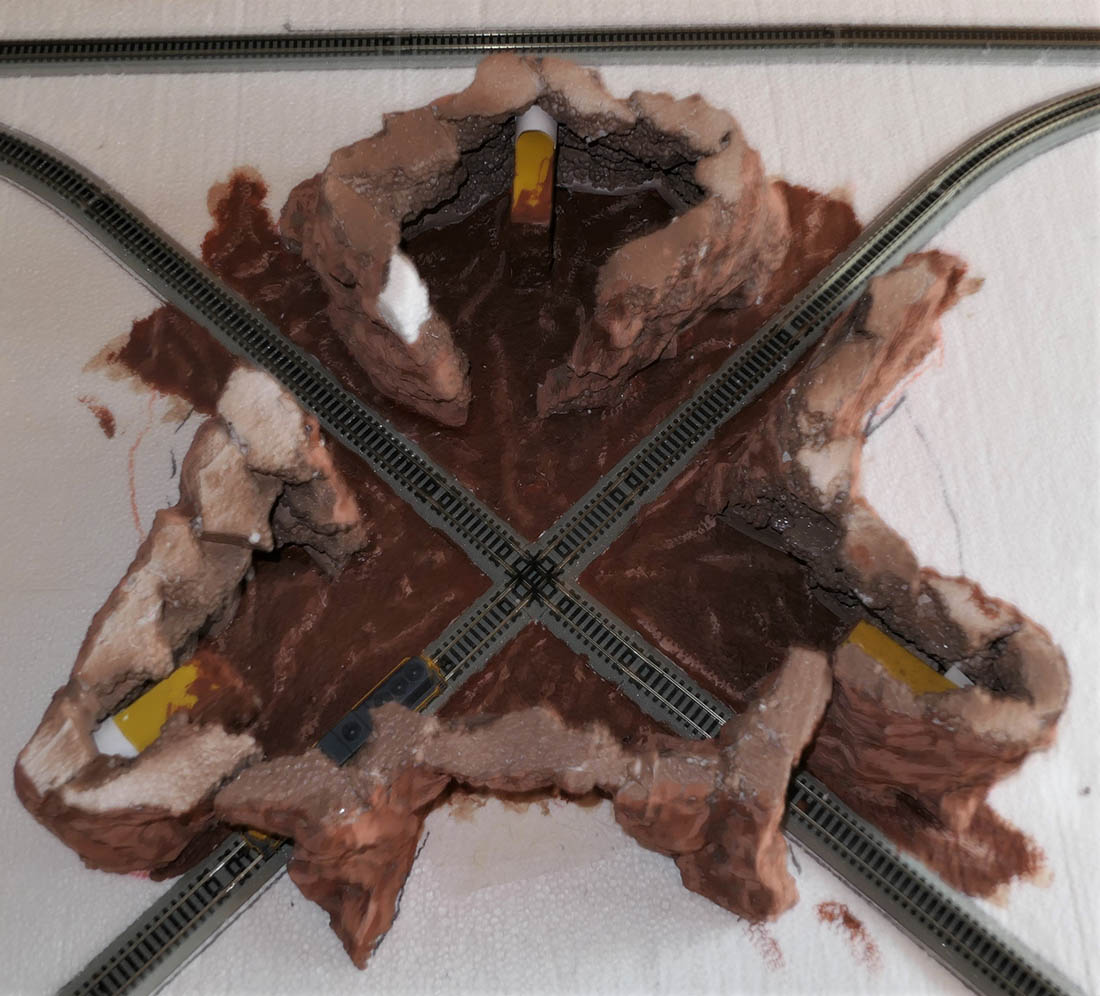
6. After outlining the locations of the walls, I used diluted white glue and toilet paper to add texture to the tunnel floor.
7. Here is a shot of the painted cave floor with the mountain walls glued in place.
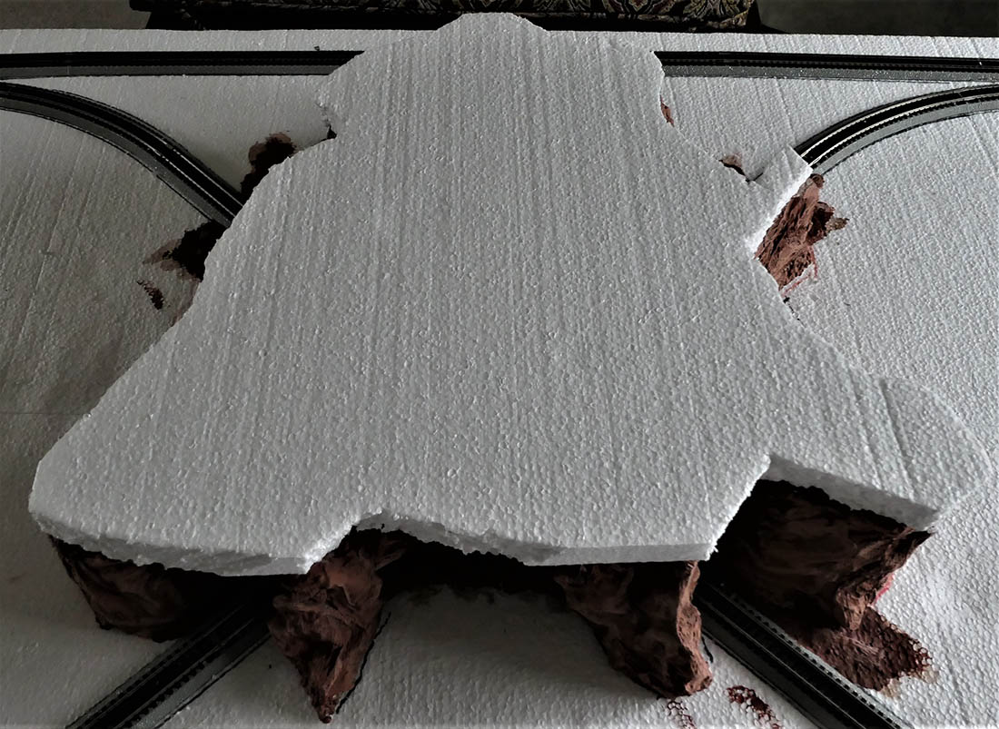
8. Next, I cut foam for the tops of the entrances and a center piece for the top of the tunnels or cave. The entrance tops will be glued in place while the center piece is a friction fit.
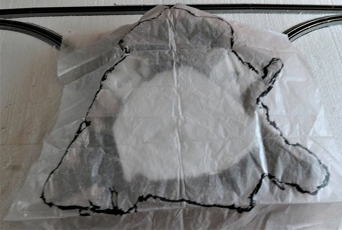
9. I used tissue to trace the outline of the mountain walls and then cut a sheet of foam to match the tracing.
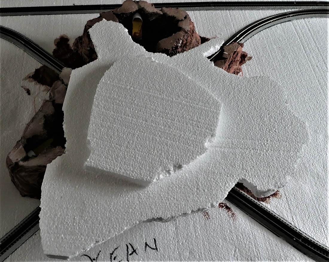
10. The piece that fits inside the mountain is then glued to the piece that serves as a base for the top of the mountain.
11. Turn the piece over and it fits snugly into the mountain base.
12. I built up the mountain top and prepared it for the lighthouse. The village to the left is Sunnydale, and the village on the right is Forest Falls. Pete’s dragon Elliott is sitting in his cave, anxiously awaiting his apples and a cocktail by the beach. Sunnydale, a happy little cul-de-sac, will have a gondola ride to the top of the mountain.