Slowly but surely there are more and more Arduino model train projects being submitted.
This is how Tim solved a problem with his turnouts:
“Al – I was inspired by a story you published about using servo motors to control turnouts. I did some research after reading this story and considered that using servos might be a viable option to replace the traditional solenoid motors in my current model railway.
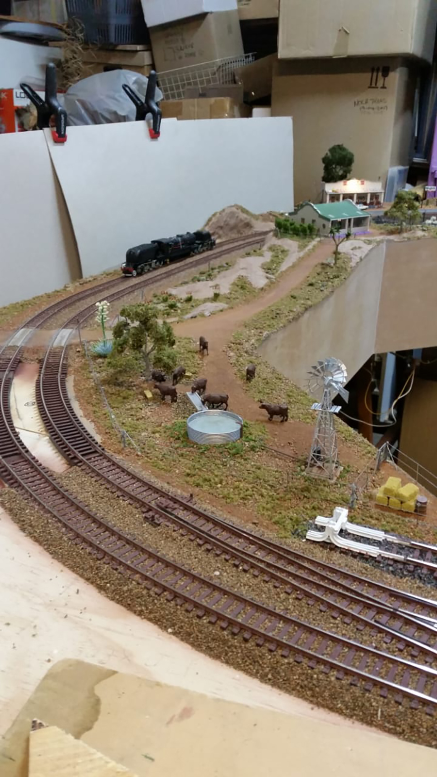
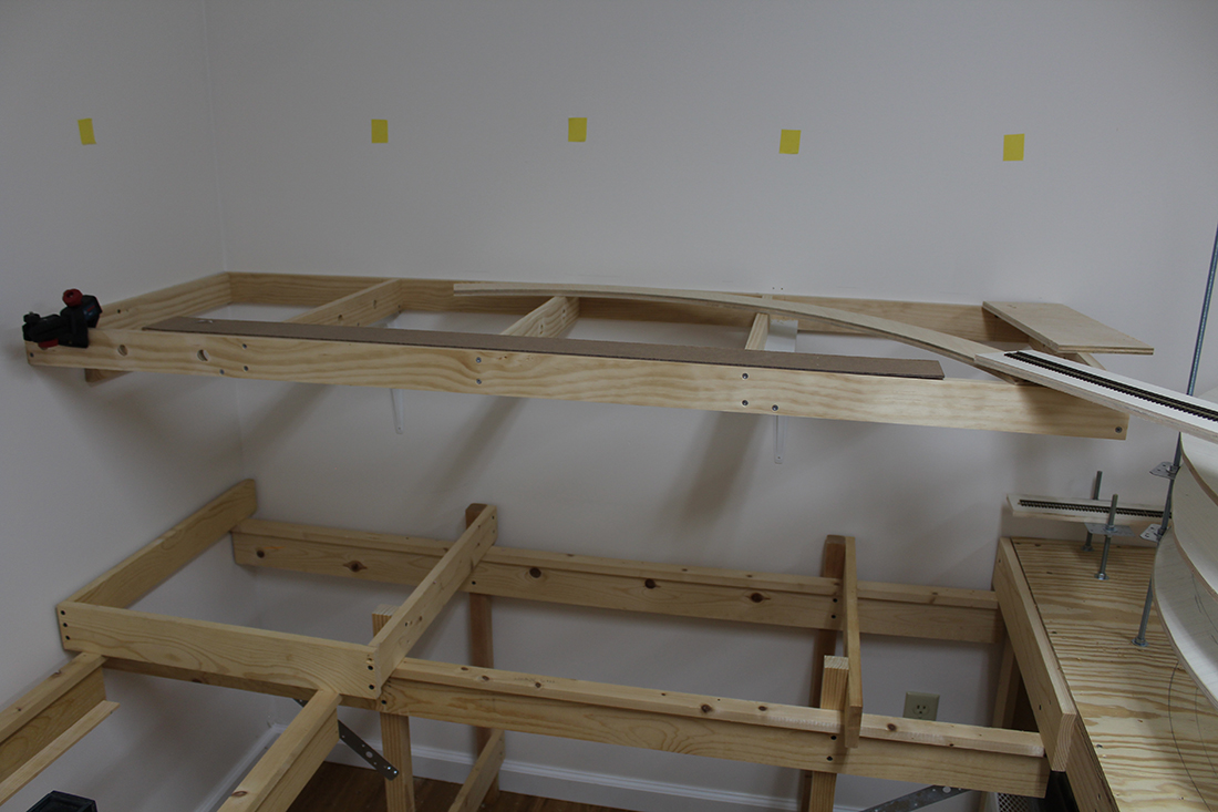
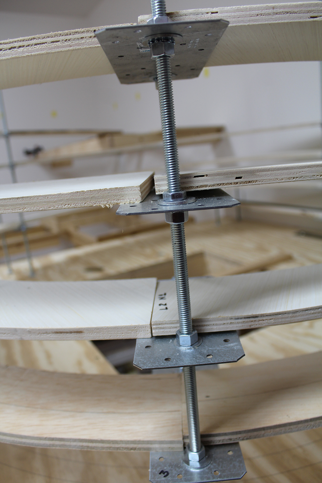
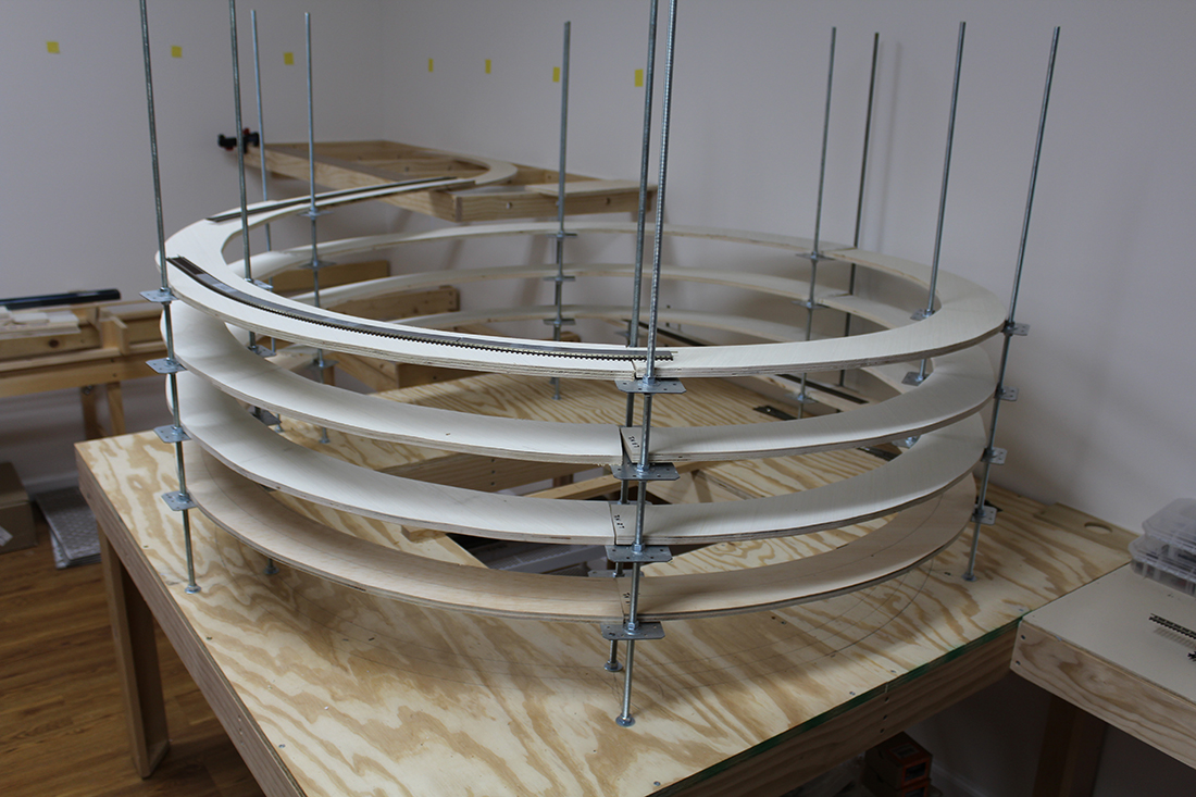
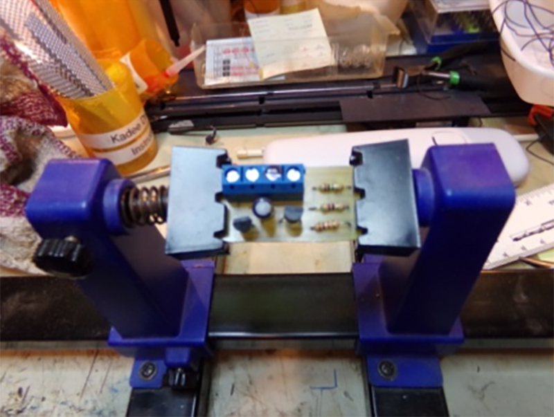
I currently use the stud and probe method with nuts and bolts through my baseboard in the design of the track (photo below).
Solenoids were relatively expensive and due to the age of them, there were occasions when they would get stuck.
However, the method of controlling these servos seemed cost prohibitive given the cost of the controllers used to activate them. It seemed to me that the maximum numbers of servos that could be controlled by one control panel was 12 and they were expensive to purchase.
After doing further research (and with the aid of my extremely talented son) I believe that I have come up with a very cost effective solution.
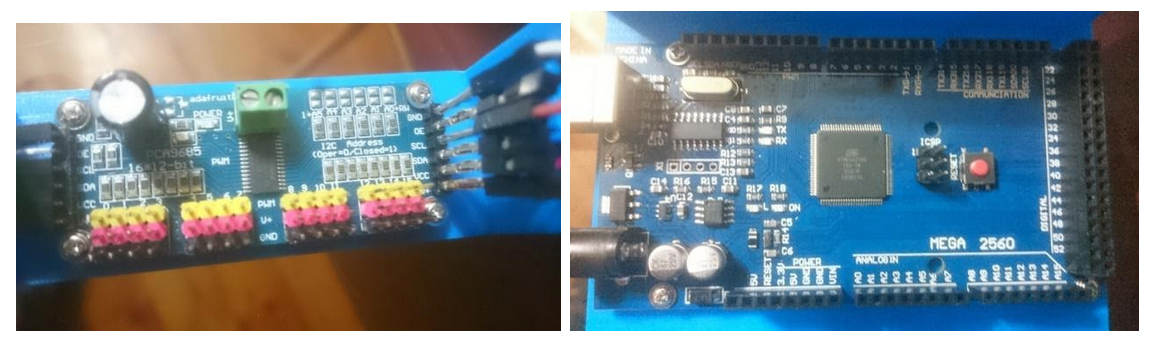
Firstly I purchased an Arduino mega for about AU$14.00. It has 54 inputs meaning that it can control 54 separate servos.
I have hooked the Arduino up to three PCA 9685 16 channel PWM servo drivers. These cost about AU$8.00 each. As the name suggests each board can control 16 servos. They can be hooked up in series so that the full 54 inputs of the Arduino can be used.
The servos cost about AU$2.00 each and with the costs of a power supply, dupont jumper cable connectors (so I could make my own wiring) and aluminium channel to house the servo, each turnout worked out to around about $5.00.
I used a straightened paper clip to connect the servo to the tie bar of the turnout to act as the lever to change the direction of the turnout. There are many internet articles about fitting servo motors.
My son has written some sketches (programs) to control the servo for various Arduino model train projects.
The first sets the servo at 90 degrees.
The second is to control a single servo – it is very useful to determine the angles required to change the point from straight ahead to turn.
The third sketch is to control up to 48 separate turnouts using the PCA 9685.
The input for each servo is the ‘stud’ part of the existing control set up with the probe being connected to the ‘ground’ input on the Arduino. Each time there is a connection between the stud and probe the servo moves in the opposite direction that it last moved.
Previously I had 2 studs per turnout – one for each direction. I now have one per turn out – each ‘press’ changes the turn out to the opposite side. The same results could be achieved by using press buttons although the wiring would be a little harder given that every button would need to have a common ground wire (this is achieved in my system with the probe)
The sketches (particularly the last one) allow for individual angles to be provided to each individual servo and the speed of the servo to be adjusted so that they change as fast or as slow as the modeller desires. They are down loaded to the Arduino and once downloaded the Arduino executes the program each time a button is pushed.
Replacing existing turnout motors was very simple. After removing the existing motor, I put the paperclip through the tie bar from above. I put a 90 degree bend in it so that it wouldn’t fall through. The aluminium channel was fitted from below the baseboard. I passed the paperclip through the appropriate hole and temporarily stuck the channel to the baseboard with a piece of doubled over electrical tape. After checking that moving the paperclip from side to side operated the turnout, the aluminium channel was secured to the baseboard using 2 screws.
I then put a ‘z bend’ into the bottom of the straightened paperclip, attached the servo motor and pushed it up into the aluminium channel. After checking that the servo worked the top of the paperclip was trimmed back to the tie bar level.
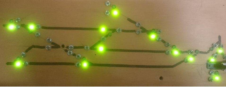
The LEDs have been wired to the side of the turnout. The inner rails of the turnout have been isolated so that the LED only comes on when the blade of the turnout is closed. That way I can see the direction and know that the blade of the turnout is closed.
This might impact on some business of the companies that have made turnout controllers but this system is far cheaper and thanks to the sketches already written it is very easy to install and control servo motors.
Hope this can be of assistance to the wider modelling community.
Regards,
Tim”
Now on to Cassio.
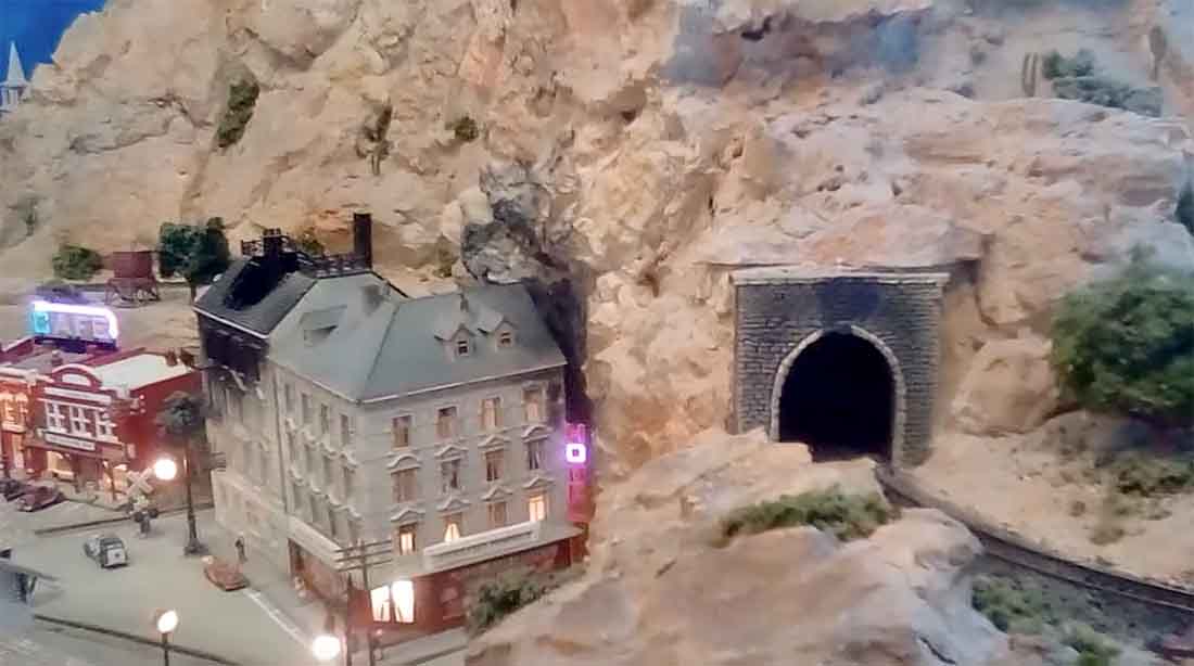
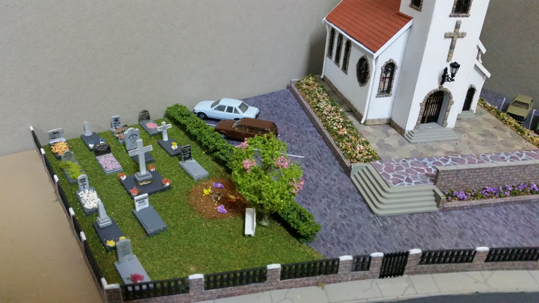
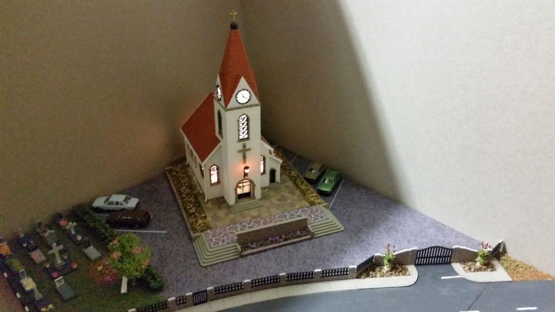
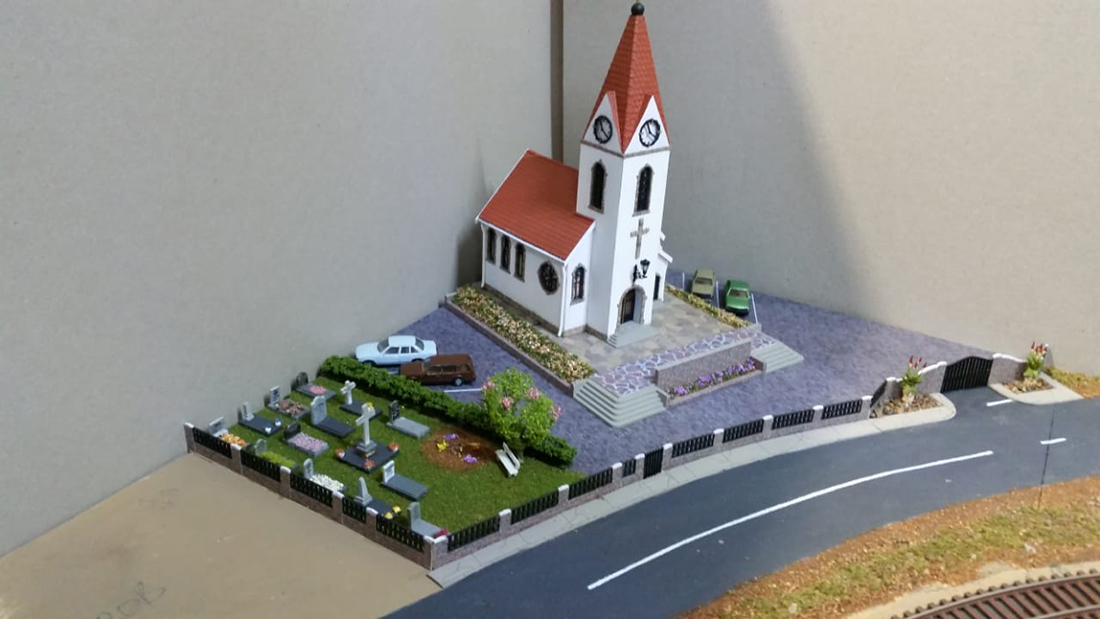
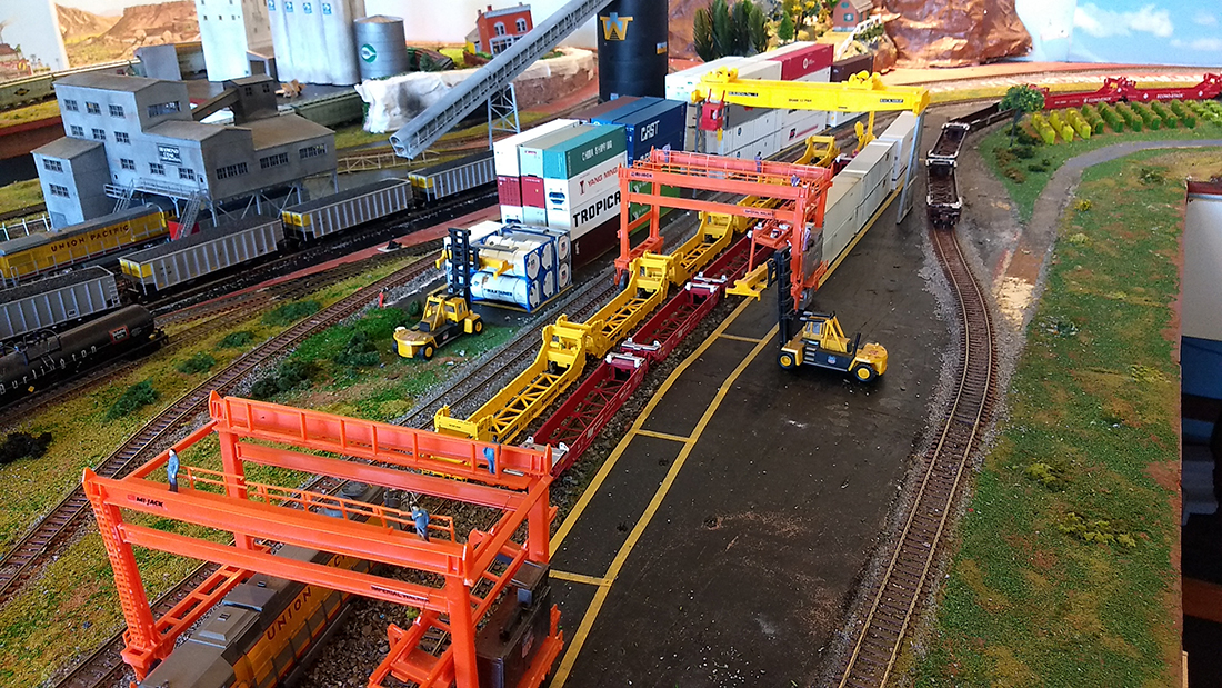
I don’t really publish pics on their own, but this one had me looking at it for a while, so I thought, why not?
You can see Cassio’s last post here.
“Hi Al , just had a day out up in North Yorkshire to see some Steam.
Thought some of the members might enjoy, as I say some saying they see too much of DMR with trains running.
Regards
Dave”
I often ask whether I’m posting too much of Dave’s stuff. I have to say the people who say ‘no’ are in the majority by a country mile, so I’ll continue to with Dave’s Model Railway.
That’s all for today.
A big thanks to Tim – I’m seem to be getting more and more Arduino model train projects, like Keith’s and John’s.
That’s all for today folks.
Please do keep ’em coming.
And don’t forget, if you want to take your first steps towards your own layout, the Beginner’s Guide is here.
Best
Al
PS Latest ebay cheat sheet is here.