Rob’s been back in touch with his stunning model London underground layout:
“Hi Al,
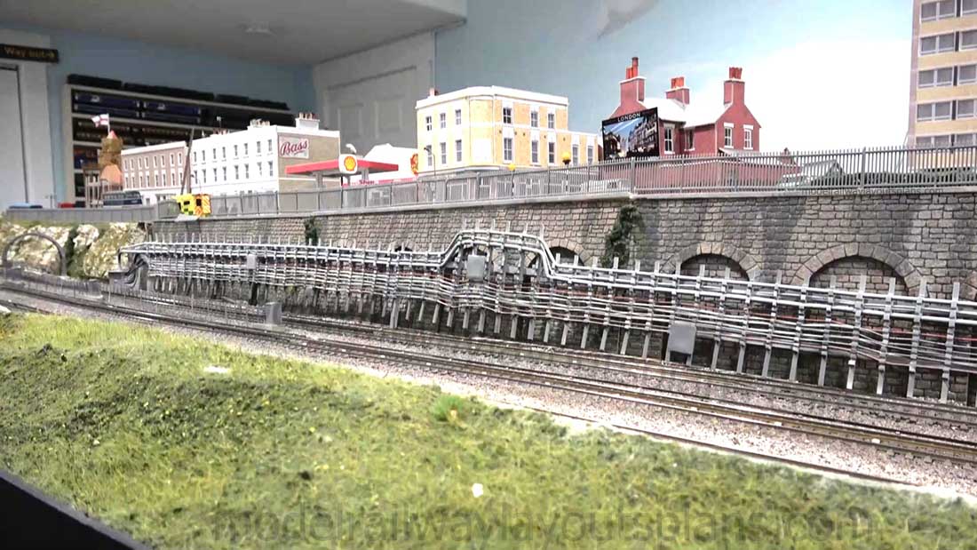
Since my last missive, I have among other things made considerable progress on my London Underground Tube Cables project.
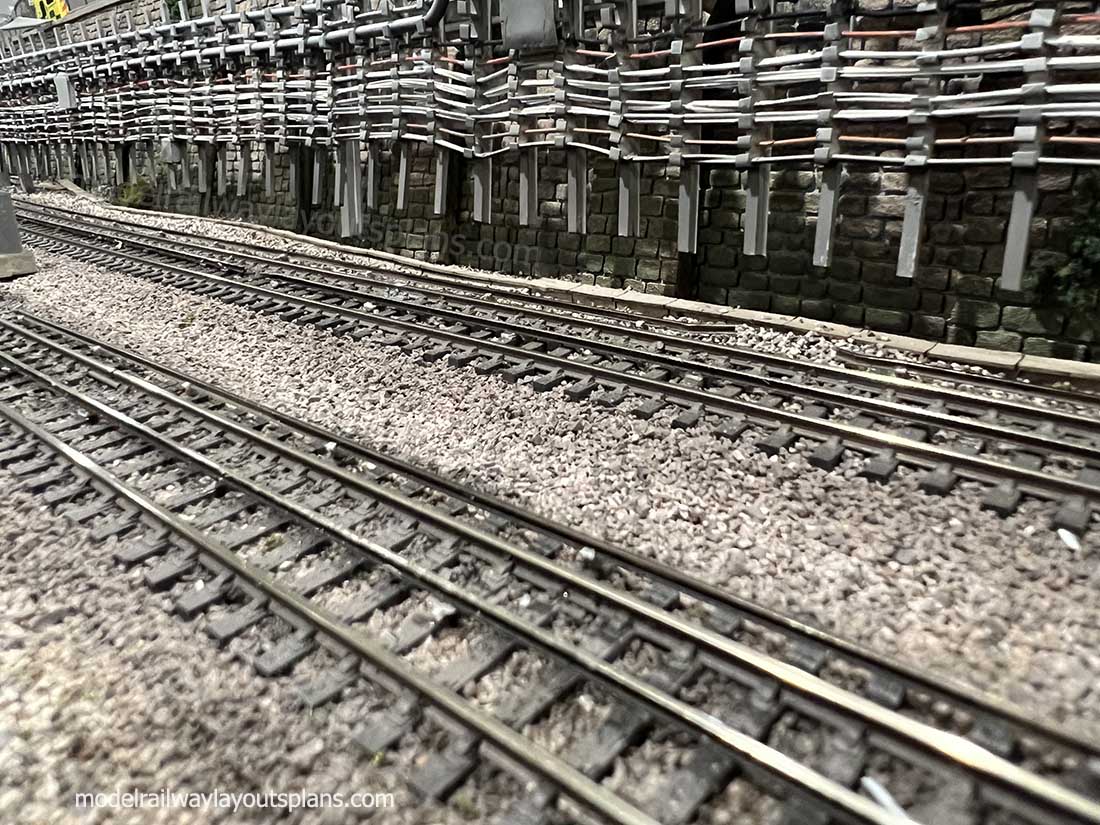
I am not finished adding the fourth rail in the center between the running rails on my two express passenger lines. I have run out of material and have some on order so I will be able to add the 4 to 5 sections of rail there in the future.
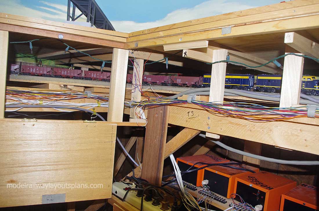
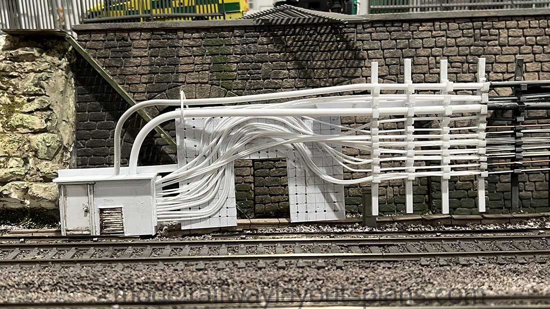
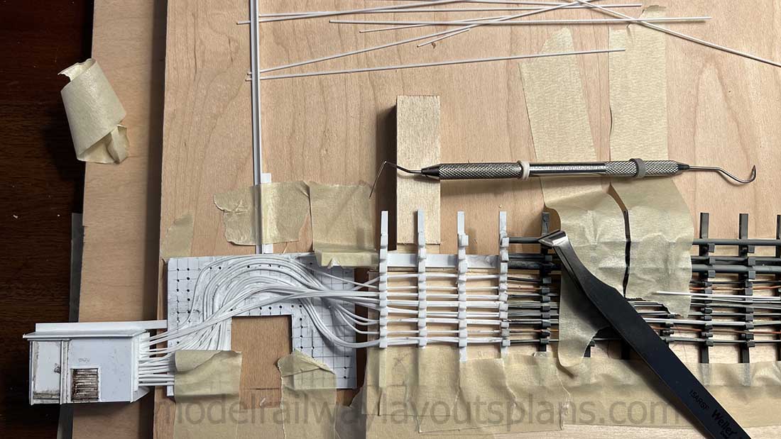
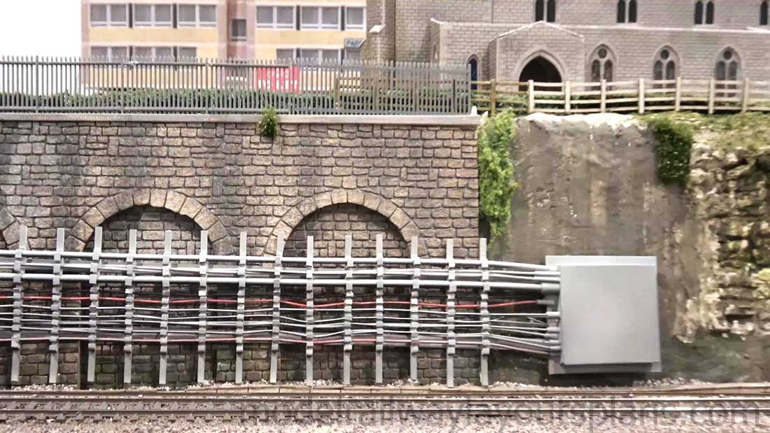
In the last video, I built two sections of the cabling hangers and in this video, I built one more section of cable hangers and cables and went on to create terminations for both ends. After all, I couldn’t just leave the cables dead-ending in space.
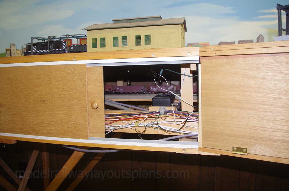
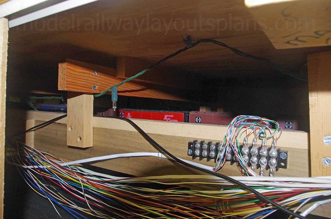
On one end I have the cables going into a large cabinet/house mounted down on the trackbed and on the other end, I built a wall-mounted box and have the cables going into that with cable connectors.
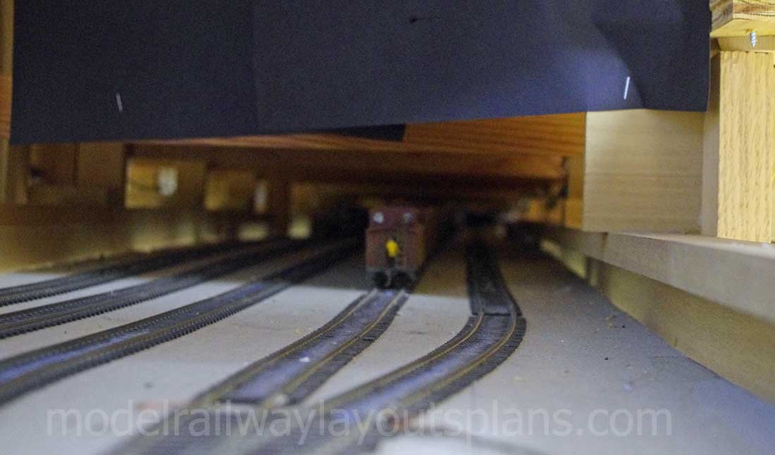
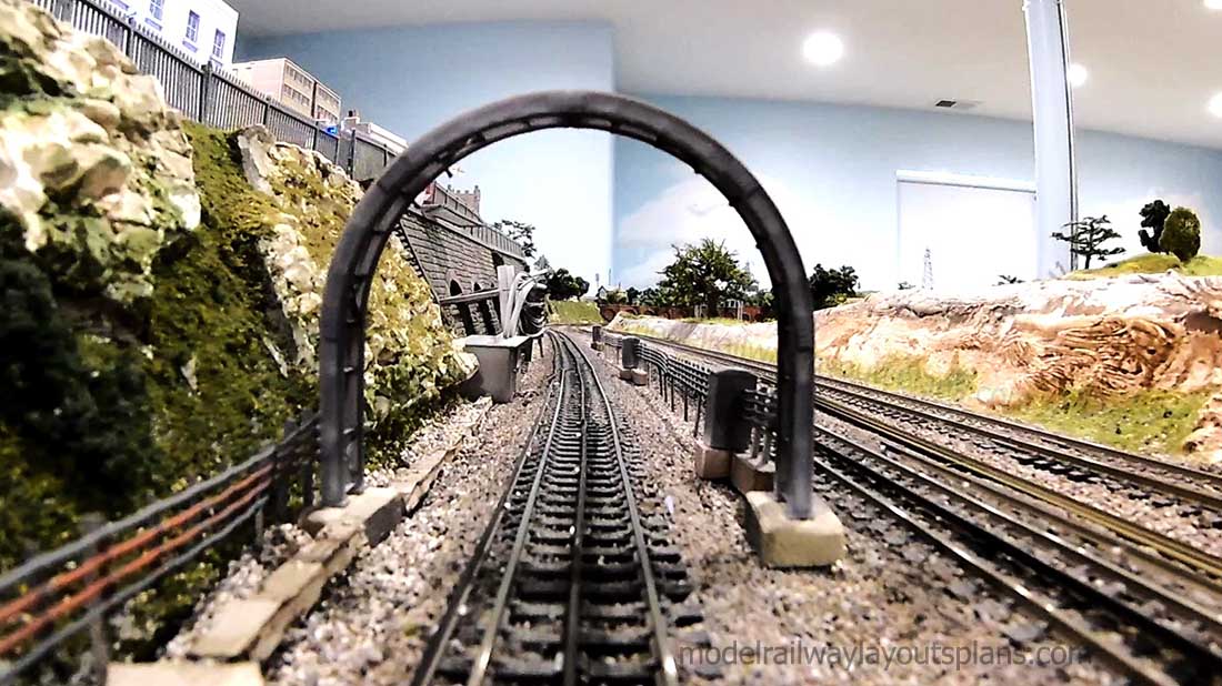
To get a close-up view of the cables with their mounting and verify I was achieving the look I wanted, I decided to mount my small camera on a truck and push it along in front of a locomotive to get the view I wanted. As a result, a cab ride was born. Who doesn’t enjoy a cab ride around a model train layout?
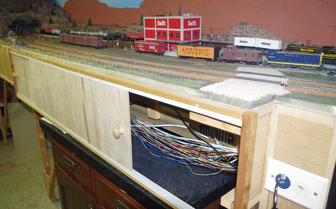
I will be finishing this whole scene up when the additional material arrives but it is very close to being completed now.
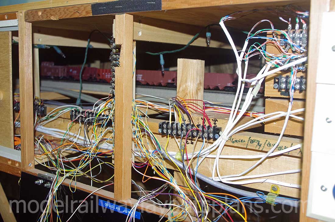
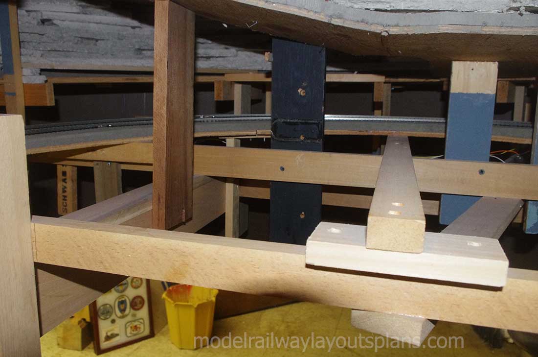
The whole cable array is one piece and is quite solid and strong. Someday, if I move or take this layout down, I can salvage this element.
Thank you for this platform where modelers can share. It is a great service to the modeling community around the world.
cheers,
Rob”
A huge big thank you to Hall of Famer, Rob.
If you missed his first post, you won’t be disappointed if you have a look. It’s here:
London Underground model trains.
Now on to the silly sale – a big thank you to everyone who has bought the Beginner’s Guide for just $9 and supported the site.
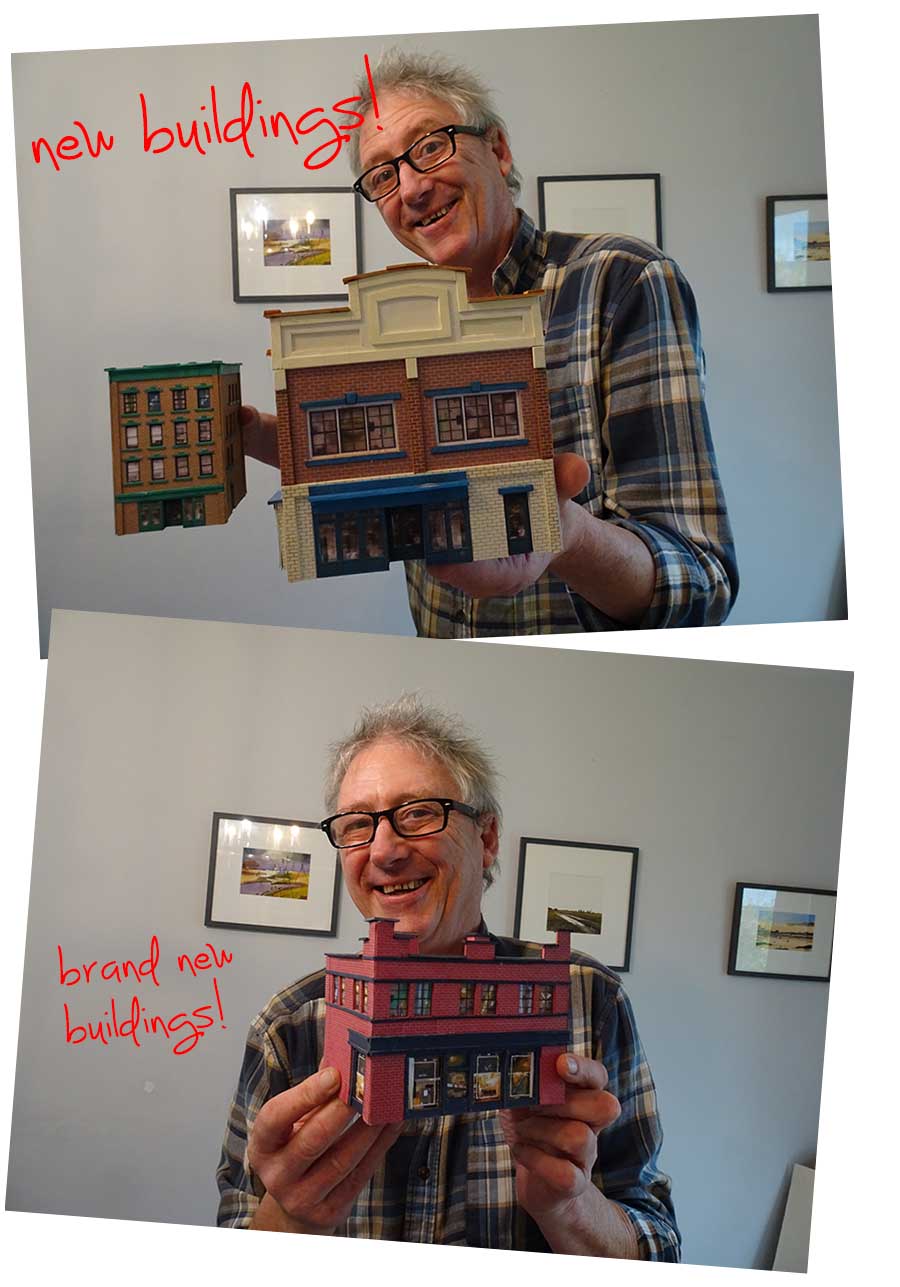
I know some of you do it just for the 3 new buildings (and that’s fine), and some of you do it just to help keep the site going.
I’m very grateful to both camps because it’s all a bit of a struggle at the mo, which is why I put this silly offer together.
You get 33 free print out buildings with the Beginner’s Guide, and it’s just $9 for the lot. I know, crazy right?
None of the buildings sell for les than $9 in the store, so that’s $297 worth of printable buildings.
Then there’s the Beginner’s guide which sells at £27 – but it’s just $9 until Monday – so you are saving a whopping $315.
Of course, I’m biased, but it’s a crazy deal.
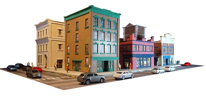
And just to show how much fun you can have with printable buildings (they are brilliant to dip your toe in the water with this hobby), here’s a small selection of them on layouts:
“Al, like you I have been retired for some time now.
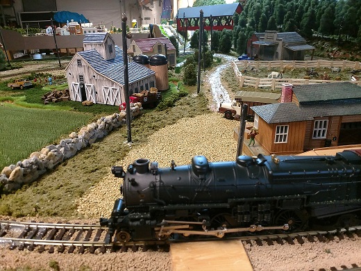
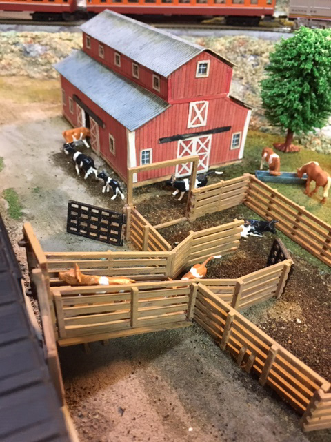
I have gone back to my American Flyer, s Guage boyhood train.
I have had “n guage, HO, G scale”, and this American Flyer has been the most fun of all. I guess it takes me back to my parents basement where my 4 x 8 foot layout was back in the early 50’s.
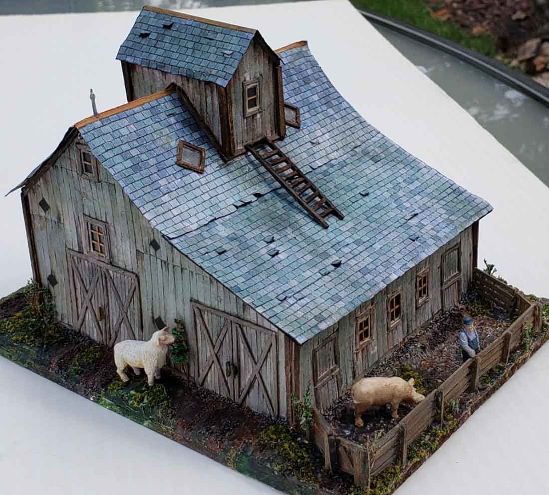
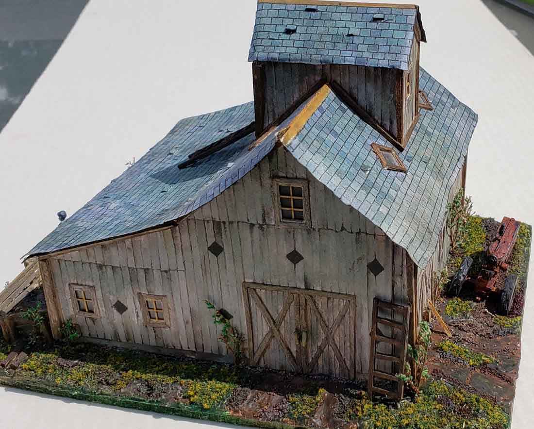
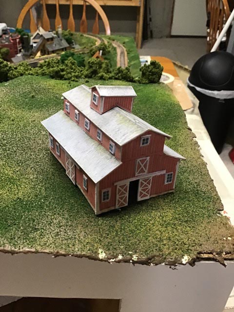
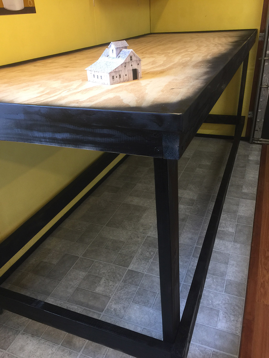
I resized your wonderful old barn and had so much fun building it. Here are some pics. Hope everyone enjoys it as much as I have.
Jerry from Illinois, USA.”
“Al,
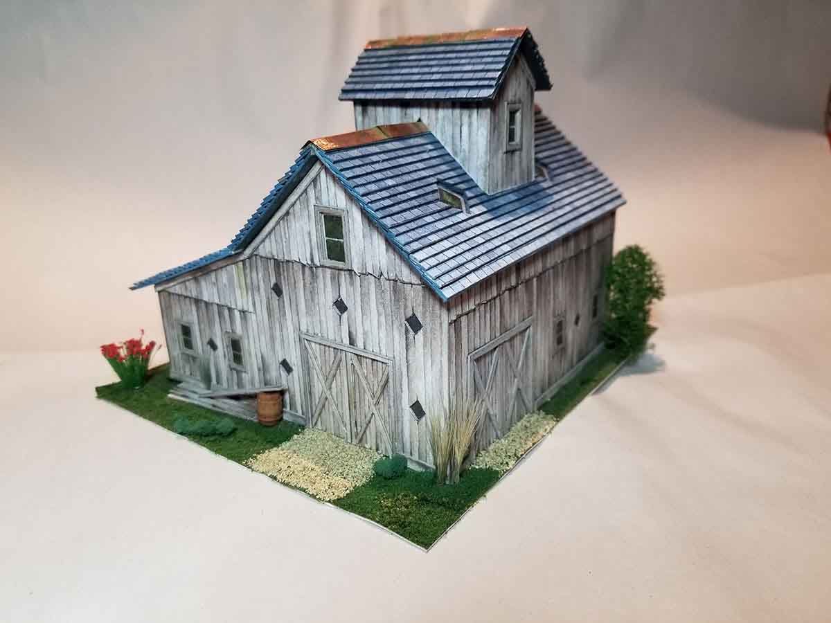
Great project and a lot of fun. The barn is on it’s way to the Railroad Club.
Charles”
“Al
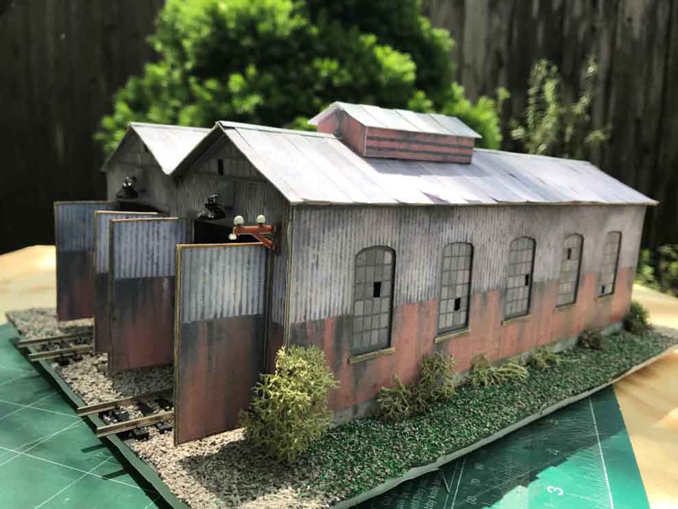
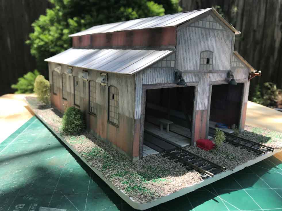
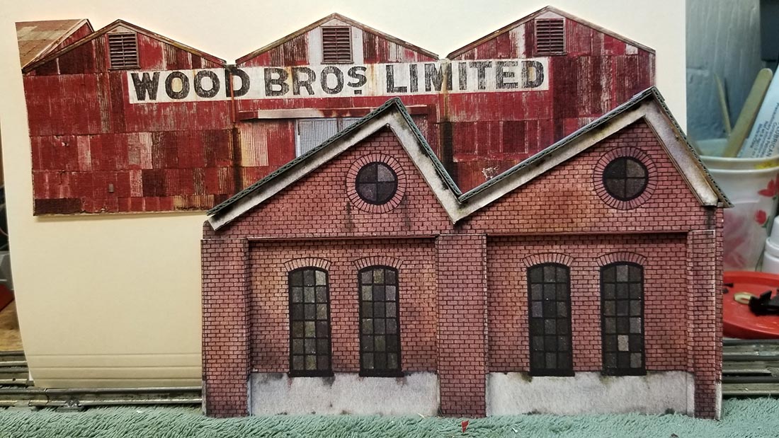
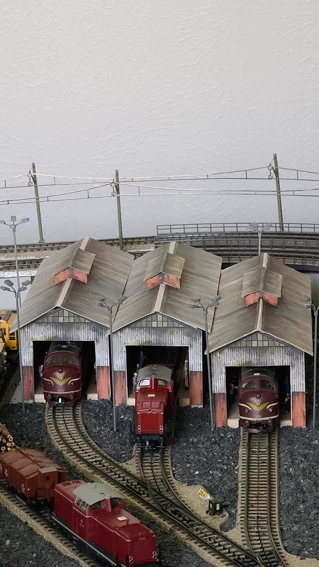
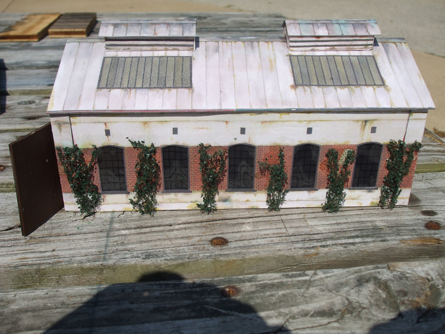
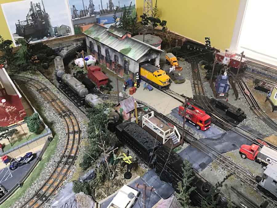
I have enjoyed your site for a long time, since I have retired had to find something to fill the spare time, I purchased one of your bundles and printed out one of the Engine sheds among many others.
I have created my own version of the Engine shed as shown in the pictures.
Side walls have ventilation fan vents.
I have dreamed to set up a model railroad layout for a long time and when I started to make it a reality one thing came up after another, like kids, education, weddings and now I have time and room to finish the dream, but not much of a budget.
Best to all talented people like Hall of Fame Dave, talented hobbyists and their many beautiful layouts.
Ryszard”
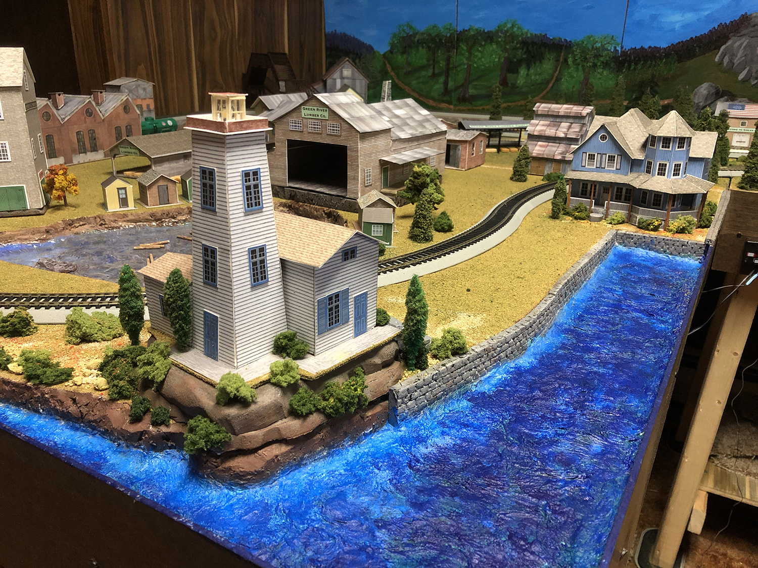
And of course, there’s lots of the printable buildings on your layouts.
Here some pictures of them:
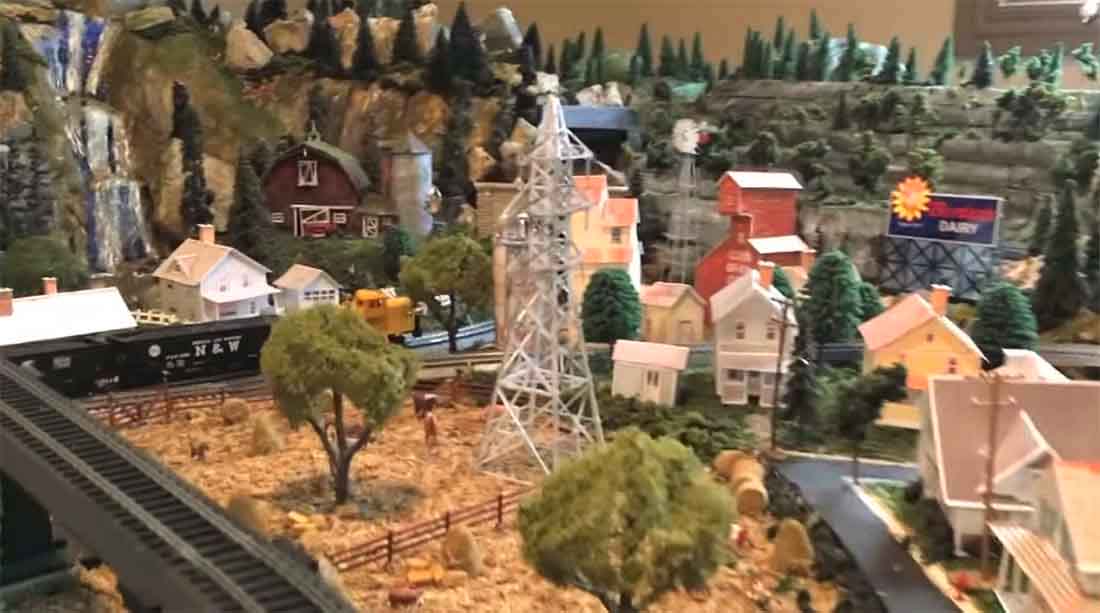
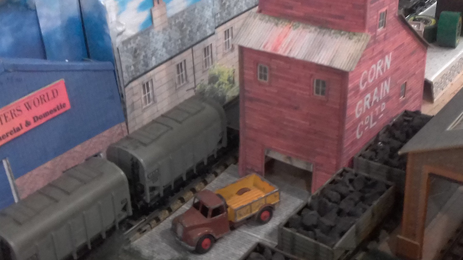
Mike has used a lot of the houses and grain elevators (not featured in the bundle – just using a print out example).
Rick’s has also made quite a bit of the printable buildings for his layout:
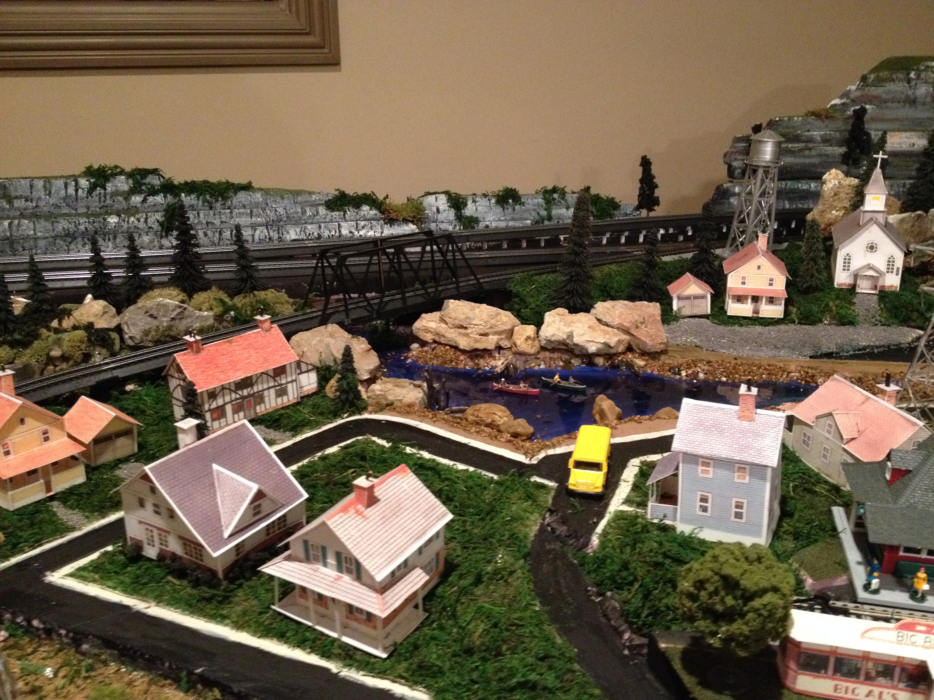
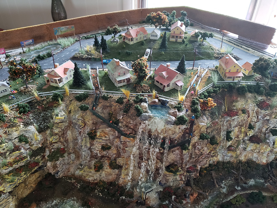
Rob has also created quite a few of the houses:
Cecil did a fab job on the Church:
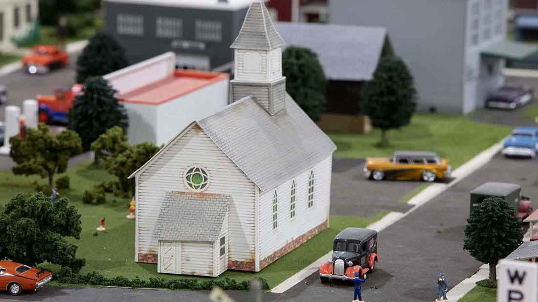
Again, the church doesn’t feature in this bundle but you get the idea.
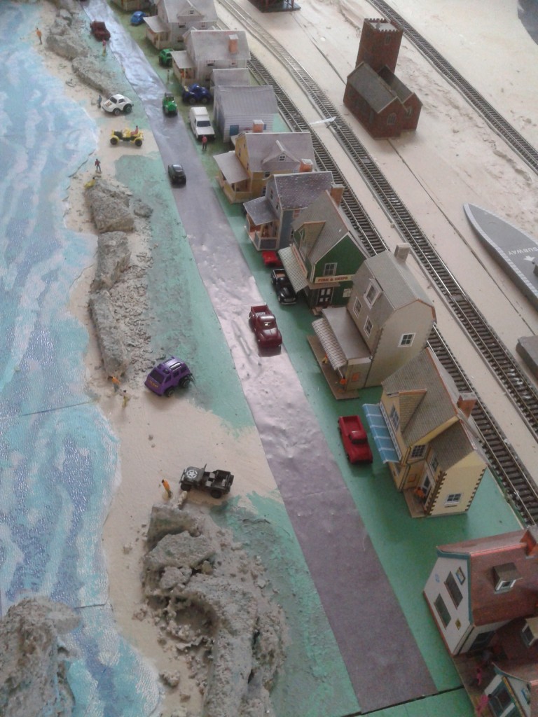
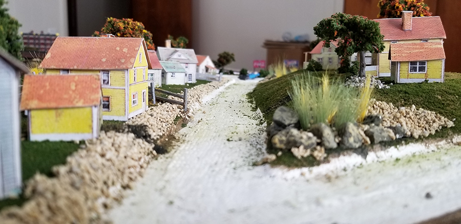
Lita has started the scenery with the houses.

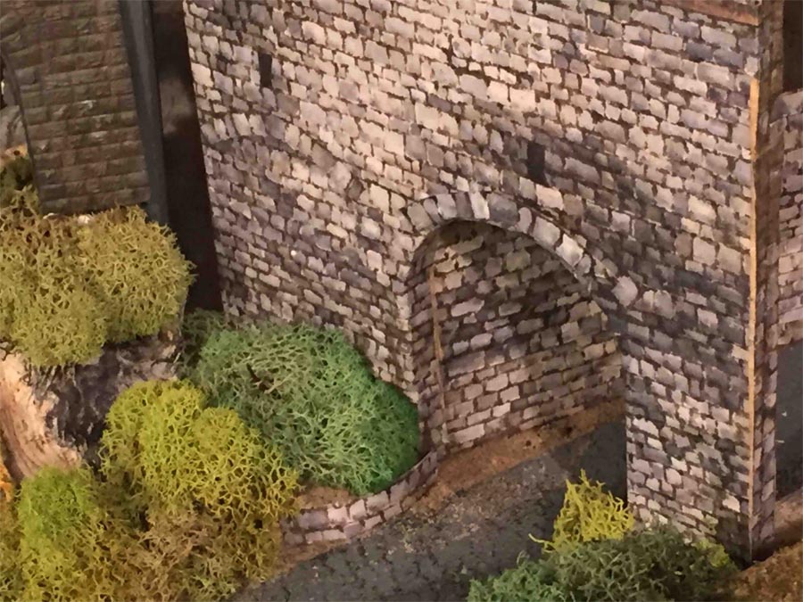
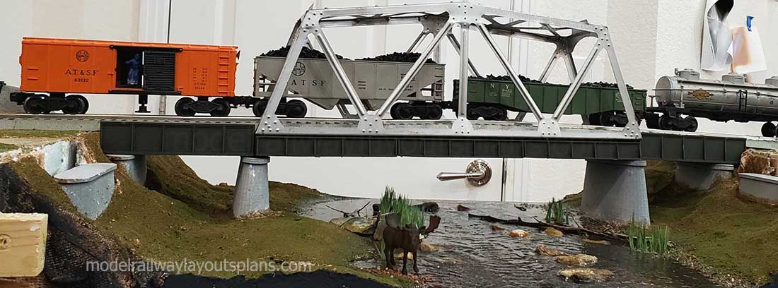
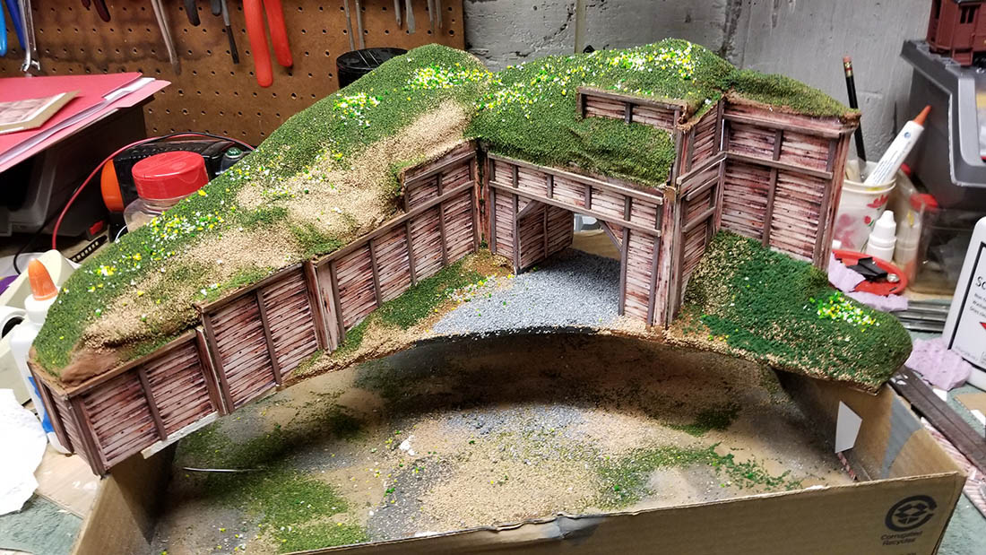
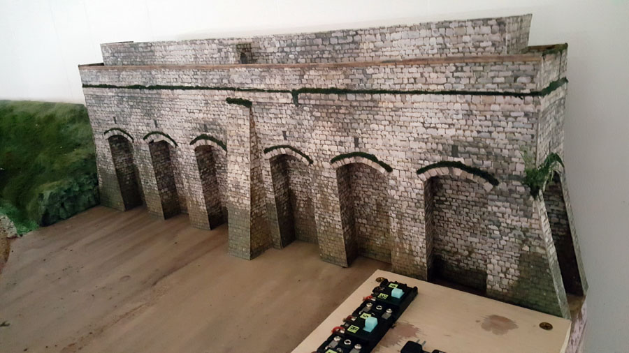
Here Glyn has used the viaduct print for a bridge base.
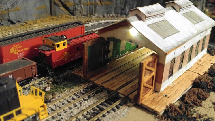
Gene adds a light to his engine shed and houses.
Rob adds a tunnel to his layout.
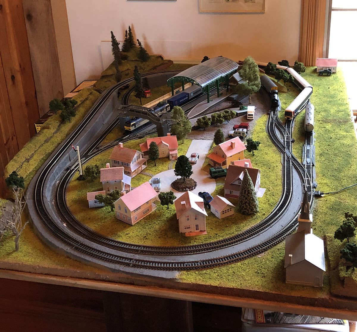
Nick’s simple layout looks fantastic.
Dana’s engine house (It’s on the bottom one of this one).
Peter’s Viaduct (it’s on the bottom of this post).
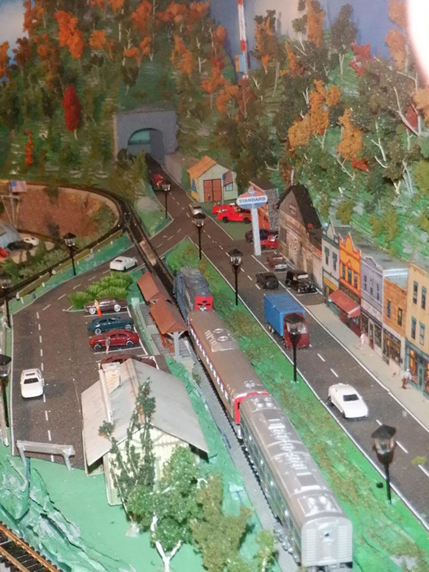
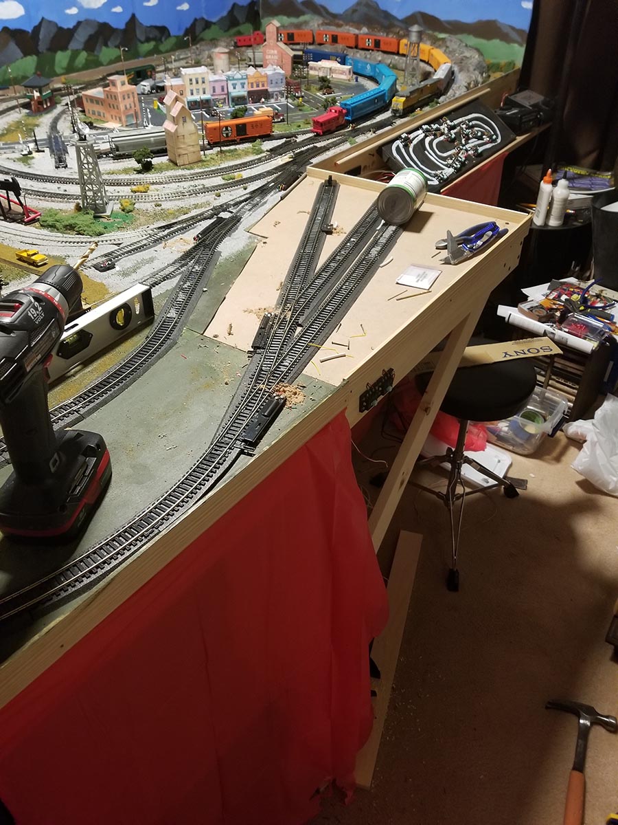
Richard’s layout has lots of the printable buildings!
Mike’s layout also has lots of the printable building on.
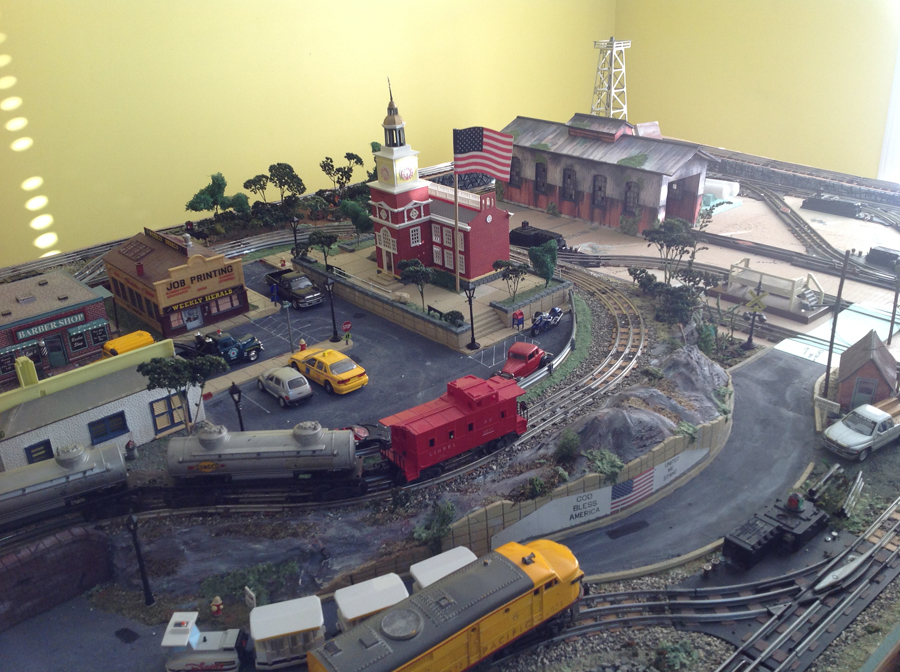
Stephen’s layout is another one with the Engine House.

Michael has done a great job on the houses.

Lots of the printable buildings on Bob’s HO scale

John’s printable building street.
There are many, many more on the blog. It really does make my day when I open my inbox and see some on a layout.
Also, they are a great way to make that all important start – and that’s what it’s all about.
Right now, until Monday, you get 33 free printable buildings with the Beginner’s Guide for just $9!.
Here’s what you get:
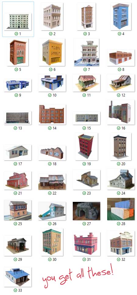
So you get 33 printable buildings and the Beginner’s Guide for just $9 – but only until Monday.

That’s all for today folks.
Please do keep ’em coming.
And frankly you couldn’t pick a better time to take the plunge with the Beginner’s Guide – it’s just $9, 33 free buildings, and you also get the warm fuzzy feeling of knowing you’ve supported the blog and helped kept the show on the road.
Best
Al
PS None of the buildings sell for les than $9 in the store, so with the Beginner’s Guide, you are saving $315 – but only until Monday!
PPS More HO scale train layouts here if that’s your thing.