Dean’s been back in touch. This time he shows us how to run a model train bus wire:
“Al, cheers from Dean in New Mexico.
I’m moving ahead with my current N-scale layout, the Santa Fe Northern, with a new and improved wiring system.
When I first started running trains on the layout, I got away with just two wires between the DCC power pack and the rails. This worked fine, but I knew that with the length of the track in the layout (loop is about 60 ft long) and the number of rail joiners (close to 50 with the Atlas flex track), I would eventually have problems with operations coming from loose joiners.
In my YouTube video referenced below, I talk about different wiring systems for model railroad layouts using either DC or DCC power. The ideal way to improve the wiring is to use a wiring buss with multiple feeders running to the track. With this system, you use a pair of larger wires (12 to 16 gauge) following the main line.
Then you add several pairs of smaller gauge (18 to 22 gauge) feeder wires to the track every few feet. There are some modelers who prefer to wire a set of feeder wires to each track length, but I feel that is overkill.
If you count the feeders in the next diagram, you’ll see I put in 11 sets. In the future if I have problems with a piece of track, I’ll just add feeders to the problem length.
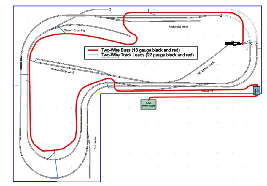
You can see my wiring diagram below. The Santa Fe Northern is a double loop, up and over, layout. It has a length of 102” and a width of 72”. I used 16-gauge wire for the two buss wires (shown in bold red) and 22-gauge feeder wires (thin blue lines).
The total length of the buss is around twenty-five feet, so, the total resistance of both buss wires is about 0.2 ohms which is small enough not to cause too much of a voltage drop.
Actually, the system is much more complex since you have the rails and multiple feeders—the resistance is very difficult to calculate, but 0.2 ohms is an upper value. Note that if I had a larger layout with bigger locos in HO or O scale, Iwould use a larger gauge wire for my buss.
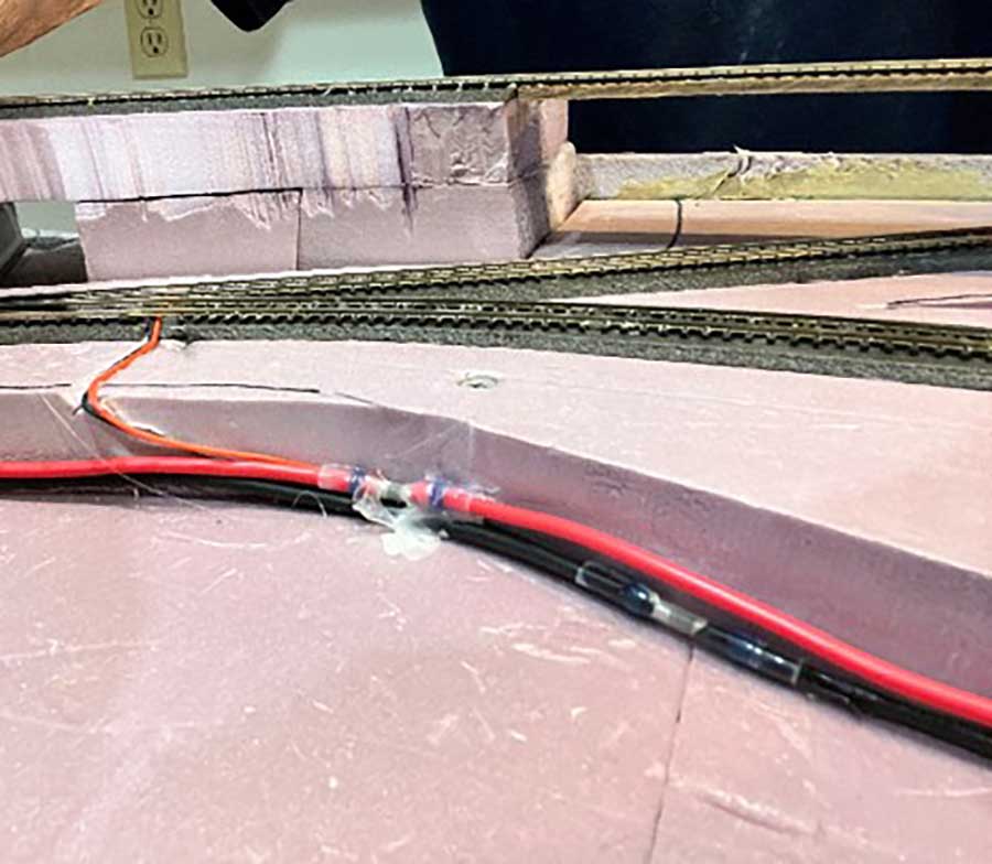
You may remember from my previous videos on the Santa Fe Northern that I used two layers of construction foam to support the layout. The lower 2” baseboard layer is flat, and the upper 1” layer, which is cut, rises and falls to support the track. You can see that in the next photo.
I don’t like to run anything under the bottom baseboard since I’m too old to be working upside down on the floor on my back.
You can also see the buss wires which run along the top of the baseboard and the smaller feeders running to the track.
These will eventually be covered with scenery as I progress but will always be accessible if I need to add more feeder pairs.
I used red and black wires consistently for all wires to keep from making wiring errors—the red buss and feeder wires are attached to the outer rail of the track with the black wires to the inner.
In most cases the feeders were soldered to the rail joiners as I lay down the track. In that way, they will be invisible after I ballast.
The feeders were attached to the buss wires with TICONN connectors which are shrinkable connectors that solder the wires together as they are fused. You can buy these, and a heat gun, from Amazon.
The red feeder wire always runs to the outside rail. Each time I added a feeder, I checked the resistance between the wires with a volt-ohm meter. If there was a very large resistance (megohms) between the red and blue wires, I knew I was ok.
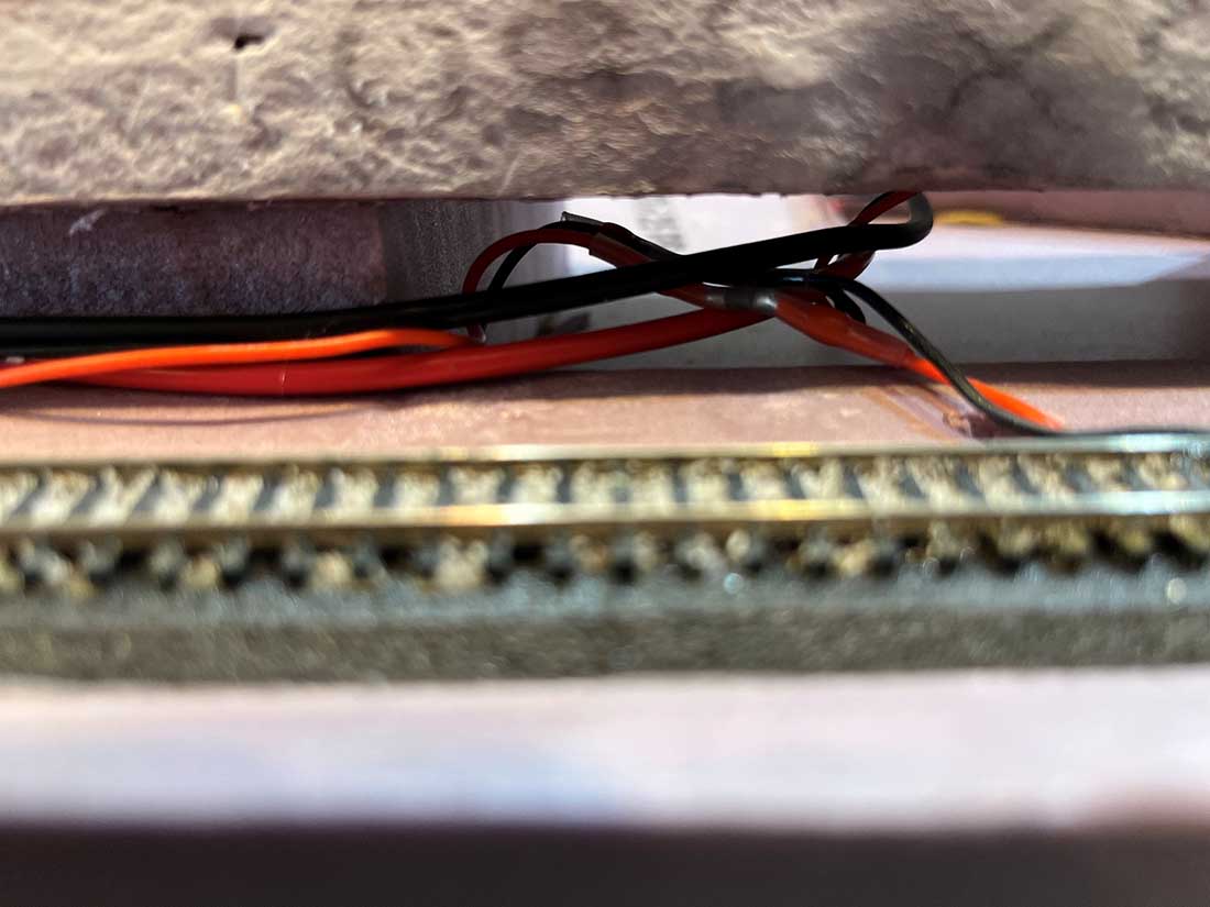
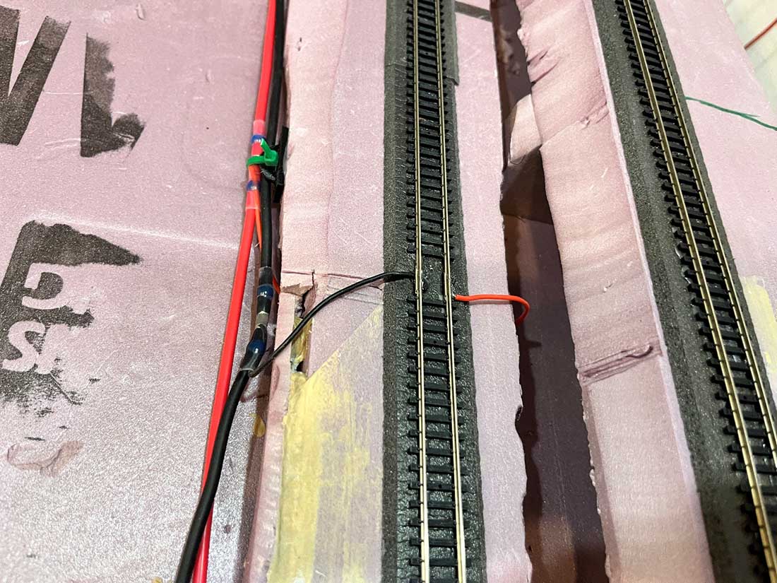
Next is a picture showing the wires at the start of the buss system (arrow in the first photo above). At this point both tracks will be inside a tunnel, so I didn’t hide these feeders. As mentioned, the feeders were soldered to rail joiners as I laid the track.
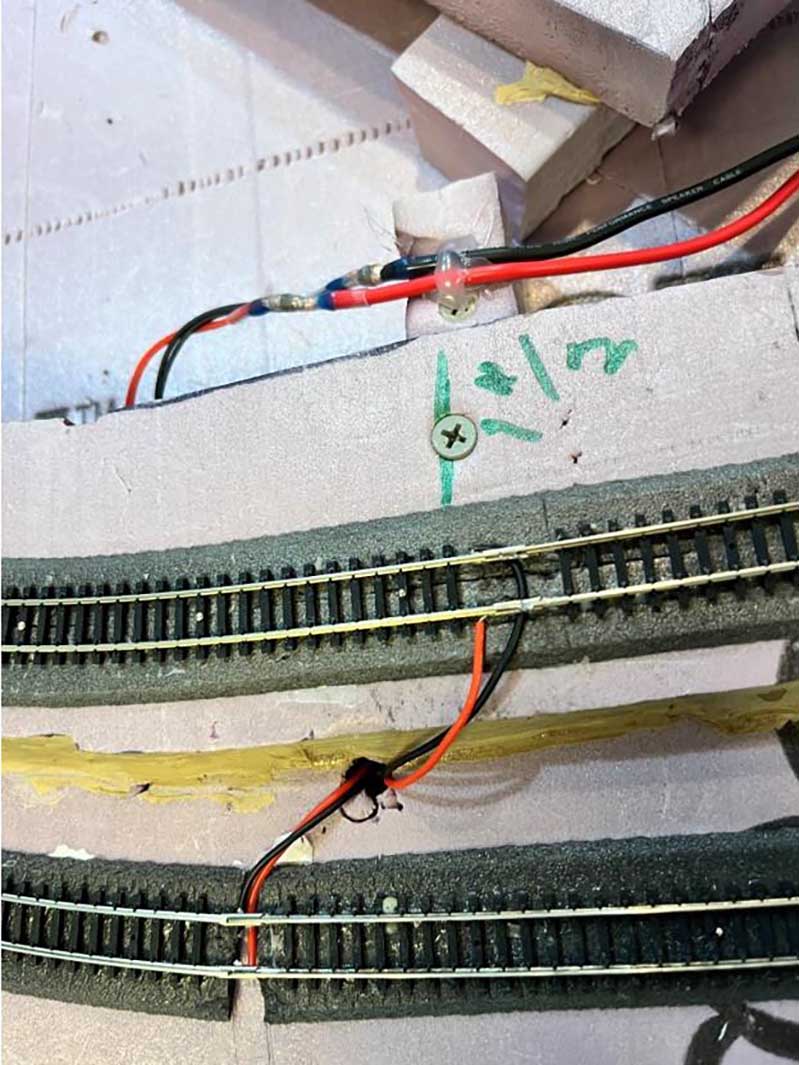
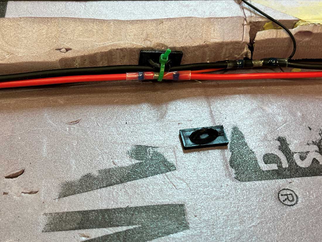
As you can see in the photo above I first fastened down the buss wires with hot glue. Later I used the black holders along with zip ties (blue) shown in the photo below. I printed out these holders on my 3-D printer and they were attached to the foam with hot glue. I whipped out the design for the 3-D parts in a few minutes using Tinkercad. Once I had the 3D file I could print these out in a few minutes on my 3-D printer. If there is interest, I will put the .stl file on the internet so that readers can print their own holders.
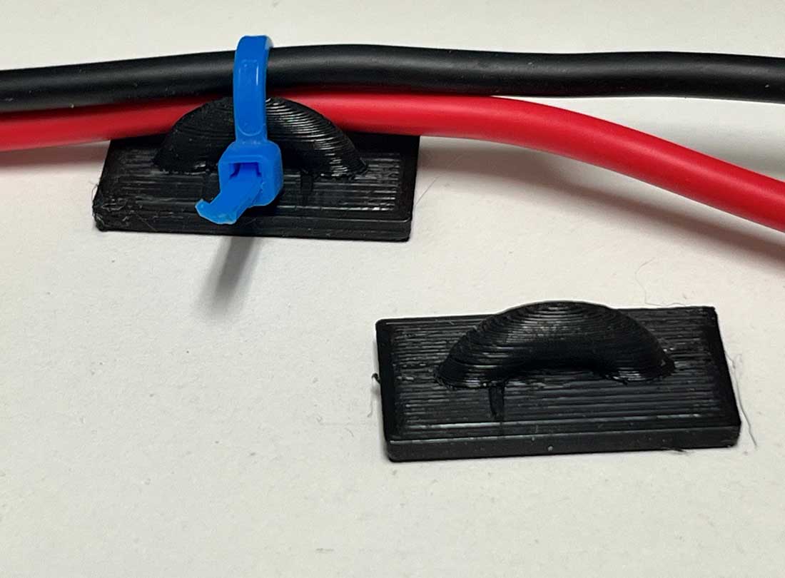
In this photo you can see how they neatly hold the buss wires.
More photos of the wires: Two groups of feeders tied to the buss (will be inside a tunnel accessible from the back of the layout).
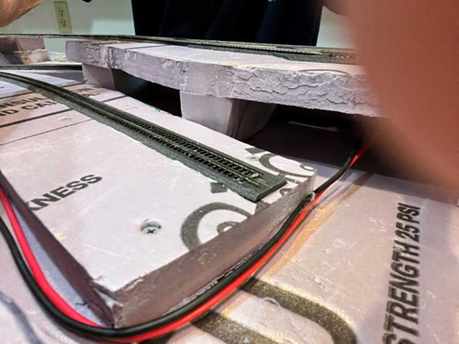
Buss wires passing around a siding at Otowi. I plan to put a river to the left of the raised area and siding.
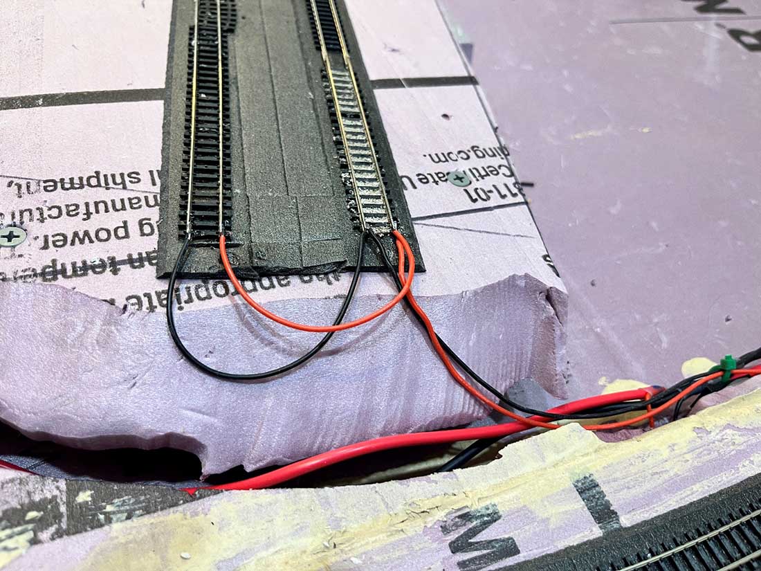
Wires from the two sidings going to the buss. The feeders were soldered to the ends of the rails in this case and the wires will be covered with scenery.
More wires soldered to rail joiners. These wires will be hidden in cuts to the roadbed and foam.
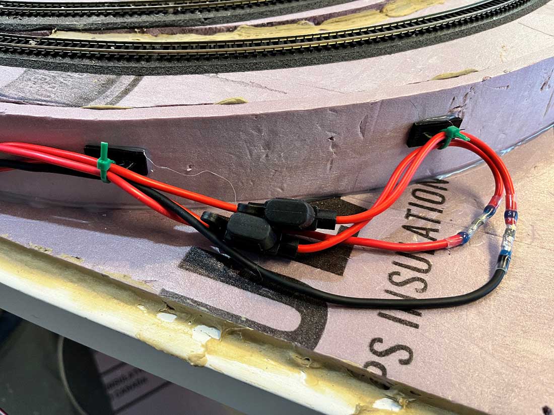
My DCC power supply cuts out if there is a short. However, for added safety I put two 2-amp auto fuses and holders, one in each of the buss leads. As shown in the original wiring diagram, these are in a space that will be accessible behind a facia board. But I don’t expect them to ever blow
I hope this shows you better my approach to wiring. In my YouTube video
You can find much more info as well as links to videos on TICONN connectors and soldering techniques.
Thanks, to all of you who are following progress and to Al.
Dean”
A huge big thanks to Dean for showing us how to run a model train bus wire.
If you want to see his previous post, it’s here: N scale track bed.
Dean has also sent in another fab post on wiring: Wiring a model railroad.
And there’s quite a few post on wiring your layout on the blofg too:
That’s all for this time folks.
Please do keep ’em coming.
And if today is the day you get started on your layout, the Beginner’s Guide is here.
Best
Al
PS More HO scale train layouts here if that’s your thing.
Need buildings for your layout? Have a look at the Silly Discount bundle.

If starting from scratch on a larger layout, I recommend sending two sets of bus wires in opposite directions, so the longest distance from the power source would be halved (with corresponding reduction in the maximum voltage drop due to resistance in the bus wires).
I like the suggestion it the TICONN connectors. I suggest that soldering the feeders to the rails, admittedly harder to hide than on the connectors and more so on N scale, helps avoid loose connectors issues. Beautiful work and detail, as usual.
Dean, very nice photos and video on buss wiring for DC and DCC. One thing I noticed in the video, I think it was in the 9th photo for the bottom of the L curve on the layout, is the red feeder wire is sticking above the ties of the track. Won’t that cause problems with couplers that could catch on that wire and cause a derailment?
Also, regarding the TICONN connectors: are you cutting the buss wire at each point where you’re attaching a feeder? It seems like you’d have to in order to slip the TICONN shrink tube over the buss wire. Doesn’t that introduce more chance of failures than using suitcase connectors for attaching the feeders to an uncut buss wire?